







- Multi-scale Progressive Fatigue Damage Analysis of CFRP Laminates Based on Micromechanics
Bowen Zheng*, Gun Jin Yun**†
*Department of Aerospace Engineering, Seoul National University
**Department of Aerospace Engineering, Seoul National University, Institute of Advanced Aerospace Technology, Seoul National UniversityThis article is an open access article distributed under the terms of the Creative Commons Attribution Non-Commercial License (http://creativecommons.org/licenses/by-nc/4.0) which permits unrestricted non-commercial use, distribution, and reproduction in any medium, provided the original work is properly cited.
This study presents a unified multi-scale fatigue damage modeling approach for carbon fiber reinforced epoxy composites, implemented in Abaqus through a UMAT subroutine. Fiber and matrix dominated failure modes are described by the 3D Hashin criteria, while the subsequent coupled degradation of stiffness and strength is modeled using the Shokrieh–Lessard approach. Furthermore, Khan's modification is incorporated into the fatigue-life formulation to normalize the life parameter by transverse strength, thereby improving the representation of transverse fatigue behavior. Mori–Tanaka mean-field homogenization is used to update the effective ply moduli on a cycle-by-cycle basis. By integrating directly with the finite‐element solver, the framework captures damage initiation, stiffness degradation, and the ensuing evolution of residual strength under fatigue loading. The results show that the predicted fatigue lives are consistent with experimental data for carbon/epoxy unidirectional (UD) laminates. The proposed framework provides a practical computational approach for predicting the fatigue life of composite materials.
Keywords: Fatigue, Multi-scale, CFRP, Micromechanics
Carbon fiber-reinforced polymer composites are now widely used in high performance, weight-sensitive structure in aerospace, automotive, and wind energy applications. These advanced materials have already found their way into most critical industries. The key aspect of ensuring long-term reliability is their cyclic fatigue behavior [1,2,5-7]. Cyclic loading leads to an irreversible microscopic accumulation of damage in the composite; some initial microscopic damage, such as fiber breakage or matrix cracking, can promote macroscopic structural failure over time [6]. Thus, fatigue is a primary design consideration for CFRP components.
Fatigue in composite materials is a multi-scale phenomenon. It initiates at the microscale through fiber/matrix debonding, fiber rupture, or ply intra-layer matrix cracking. During continued loading, local defects accumulate and coalesce, leading to stiffness degradation and crack propagation at the lamina and laminate levels, eventually resulting in macrostructural failure. The macroscopic manifestation of microscale damage is a significant challenge and an active field of research. Multi-scale modeling has emerged as a powerful tool that spans multiple scales by relating the progressive evolution of micro-level damage to the composite structure's overall fatigue behavior.
One of the most important features of multi-scale analysis in this study is that micromechanical homogenization enables the prediction of effective material properties from the behavior of the composite constituents (fiber and matrix). A well-established mean-field homogenization method is the Mori–Tanaka method, which has particular advantages in this respect. The Mori–Tanaka approach provides a relatively accurate estimate of a composite's effective stiffness while remaining computationally light; hence, it is well-suited for multi-scale simulations. The procedure incorporates matrix–inclusion interactions in a composite and is known for its fair predictive capability and excellent time efficiency across a wide range of composite microstructures [3,4]. Another important ingredient in composite fatigue modeling is a robust dominated failure modes for detecting damage initiation. Hashin's failure criteria, developed by Z. Hashin, are among the most frequently used for this purpose [8,9]. The Hashin criteria identify different damage modes, such as fiber tension, fiber compression, matrix tension, and matrix compression failure, which help accurately predict the onset of failure in each mode under complex multi-axial stress states. Due to their physical basis and proven track record, Hashin-type criteria are widely accepted as efficient tools for predicting damage in composites and are implemented in multiple analytical and finite element frameworks [10-12].
Beyond initial failure prediction, modeling the evolution of material properties under cyclic loading conditions is essential for accurate fatigue life determination. Most metals have well-defined stress-life (S-N) curves. In contrast, composite materials, due to progressive degradation in stiffness and strength associated with damage, must rely on material property degradation modeling for life prediction. Such fatigue damage models include embedded property degradation rules that mathematically reduce stiffness/strength based on either the number of cycles or an evolving damage state. Shokrieh and Lessard proposed an empirical model for stiffness and strength degradation to support a simulation scheme [15,16]. In this way, such a progressive fatigue damage model can predict the residual stiffness, residual strength, and fatigue life of composite laminates under various loading scenarios, confirming that it is essential to consider degradation mechanisms in the fatigue analysis of composites.
In this study, a multi-scale numerical framework is developed for the fatigue analysis of CFRP composites, considering all of the above ingredients. The Shokrieh–Lessard degradation model, the Mori–Tanaka homogenization approach, and the Hashin failure criteria are coherently integrated into a single simulation scheme. In such a framework, the constituent material properties are updated at prescribed cycle intervals to account for stiffness and strength degradation due to damage as identified by Hashin's criteria; these updated properties are then homogenized into the effective ply properties using the Mori–Tanaka technique. This multi-scale approach thus links constituent-level degradation with the macroscopic fatigue response to provide more realistic, physically based predictions of fatigue life.
The proposed multi-scale fatigue simulation approach is validated against experimental data to ensure its accuracy. Model predictions are compared with published fatigue test results for carbon/epoxy composites; for example, published experimental data for CFRP laminates [3,16] provide a baseline for model verification. Such a comparison demonstrates that the simulated fatigue life and stiffness degradation trends closely match those of the observed experimental behavior, indicating that the model is reliable in predicting the composite's fatigue performance.
Overall, this study will elaborate on an accurate prediction of multi-scale fatigue life, particularly for resin-based CFRP composites. General knowledge will again be enriched regarding the development and evolution of fatigue damage in such materials. A linking approach between constituent-level damage modeling and macro analysis has been developed within this framework to provide insight into how constituent-level degradation mechanisms are translated into a gradual reduction in structural performance. Outcomes from this research will support the improvement of approaches for estimating fatigue life and for damage-tolerant design of composite structures to enhance their repairability and service safety.
2.1 Micromechanical theory
In micromechanics based homogenization, the Mori–Tanaka scheme provides an efficient analytical framework for estimating the effective properties of composite materials. While finite element based homogenization generally relies on numerical calculations of explicitly modeled representative volume elements, the Mori–Tanaka method derives the homogenized stiffness from the constituent properties, volume fractions, and inclusion morphology. This analytical treatment reduces the need for repeated numerical solutions and provides a computationally efficient means of characterizing the macroscopic mechanical behavior of heterogeneous materials.
Researchers such as Ju and Chen, as well as Ha and Kim [3-4,13], have adopted the Mori–Tanaka homogenization scheme to compute the effective moduli of composite materials, thereby characterizing their macroscopic mechanical behavior. The formula is calculated as follows:
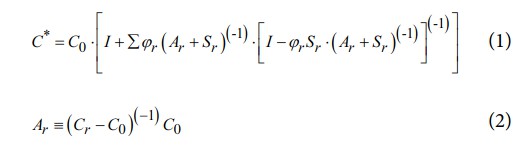
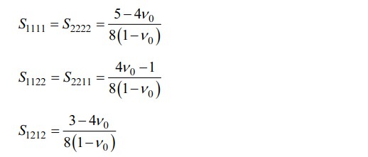
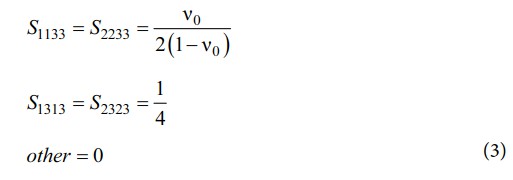
Equation (1) reduces to the classical two-phase MT solution when N = 1 and perfectly bonded inclusions are assumed. For a continuous circular fiber embedded in an isotropic matrix, S takes the well-known form Mura [14]:
2.2 Fatigue degradation model
The fatigue life of composite materials was initially predicted using S–N curves, in which constant amplitude tests performed at various fixed stress levels were correlated with the number of cycles to failure. While convenient, the traditional S–N approach provides only a nominal life estimate and does not capture the progressive degradation of stiffness and strength that develops during cyclic loading. To address this limitation, Shokrieh and Lessard introduced a cycle-by-cycle progressive fatigue damage model that couples stiffness degradation and strength reduction within a unified framework. At each load cycle, the model identifies local failure modes in both fibers and the matrix and simultaneously updates the corresponding stiffness components and residual strengths using empirically calibrated evolution laws. By explicitly tracking the progressive evolution of damage, the model can reproduce the cumulative effect of damage on the macroscopic response and has become a widely accepted methodology for fatigue analysis of composite laminates [4,15-17]. The residual stiffness of a unidirectional ply subjected to an arbitrary uniaxial stress state and stress ratio can be quantified by the empirical relation:

Where n is the current cycle count and Nf is the number of cycles to failure at the applied loading level, Es is the static (undamaged) modulus, εf is the average failure strain, and γ and λ are experimentally fitted shape parameters.
The residual strength is expressed as follows:

where Rs is the static strength, α and β are experimentally fitted shape parameters.
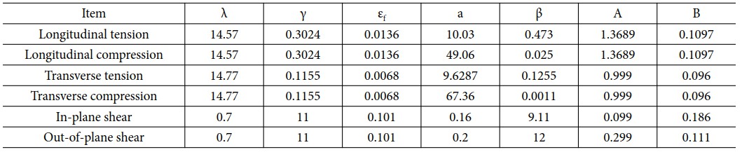
These parameters are provided in Table 1 [15,16].
Complementing this stiffness degradation law, the normalized
fatigue life of the ply is obtained from the expression proposed by Adam et al. [22]:
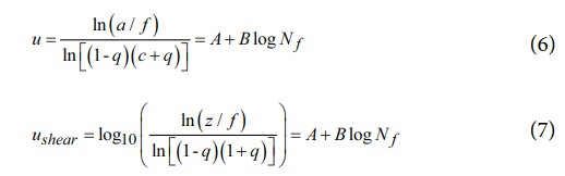
where f and u are curve fitting parameters, and the following stress definitions, the alternating stress σa = (σmax - σmin) / 2, the mean stress σm = (σmax - σmin) / 2, the normalized mean stress q = σm / σt, the normalized alternating stress a = σa / σt and c = σc / σt, z denotes the normalized shear stress.
Here σt and σc are the tensile and compressive strengths, respectively, while A and B are regression coefficients obtained from fatigue test data. Together, these equations allow simultaneous tracking of stiffness degradation and life prediction for unidirectional plies under any combination of mean stress and stress amplitude.
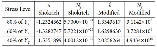
Furthermore, in the transverse direction of Shokrieh's model, Khan introduced a refinement that normalizes the parameter u by the transverse strength [17]. By explicitly accounting for compression in the matrix-dominated direction, this modification yields more accurate predictions of fatigue life in the transverse direction. Khan's proposed adjustment is as follows:

Table 2 compares the calculated values of the unified load parameters, u and û, obtained using Shokrieh’s model and Khan’s modified model.
2.3 Failure criteria
Over the past few decades, numerous composite failure theories have been proposed by Tsai–Wu, Chang, Puck, and Hashin [8,9,18-20]. This study, owing to Hashin's widespread use in composite damage and failure modeling [10,12], adopts the Hashin criterion. Its explicit distinction of six critical modes, fiber tension, fiber compression, matrix transverse tension, matrix transverse compression, matrix through-thickness tension, and matrix through-thickness compression, offers both physical clarity and straightforward integration into finite element frameworks, making it ideally suited to the aims of this work. The 3D Hashin failure criteria are as follows:
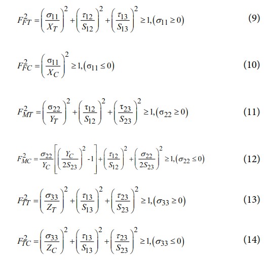
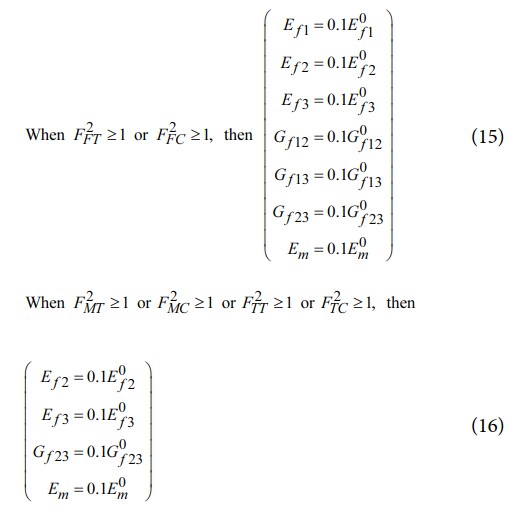
When a Hashin criterion reaches or exceeds unity, it indicates that damage has occurred in the fiber or matrix for the corresponding mode. In principle, the elastic modulus of the damaged region should be reduced to zero; however, to maintain numerical stability in the finite element solution, this study instead instantaneously reduces the modulus of damaged elements to 0.1 times their initial value. Specifically, in each load cycle, we evaluate the Hashin criteria for six modes, fiber tension, fiber compression, transverse matrix tension, transverse matrix compression, through-thickness matrix tension, and through-thickness matrix compression. Once any criterion is satisfied, the corresponding elastic modulus components are immediately degraded. This approach captures the abrupt stiffness drop due to damage while preventing stiffness matrix singularities, thereby ensuring both convergence and simulation reliability. The sudden degradation upon failure is as follows:
3.1 Finite element analysis
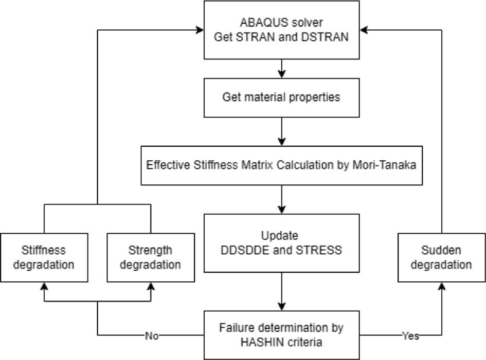
Building on the framework outlined above, the proposed multi-scale fatigue damage methodology was encapsulated in Abaqus/Standard via a user subroutine (UMAT). The UMAT integrates the 3D Hashin failure criteria, Mori–Tanaka homogenization, and Shokrieh and Lessard stiffness and strength degradation laws into each integration point, allowing the finite element solver to update constituent properties on a cycle basis. The process is shown in Fig. 1 Through this implementation, the model can capture damage initiation, abrupt modulus reductions, and residual strength evolution under arbitrary loading histories, thereby enabling reliable fatigue life prediction for composite structures.
3.2 Comparison with experimental data
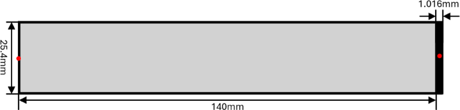
In this study, the specimen geometry and experimental data were adopted from the configuration presented by Shokrieh et al.[16]with its dimensional details shown in Fig. 2. The red points denote reference nodes used to enforce coupling constraints on the two end faces. One end face is then assigned a fixed boundary condition, while a uniaxial load is applied to the opposite end.
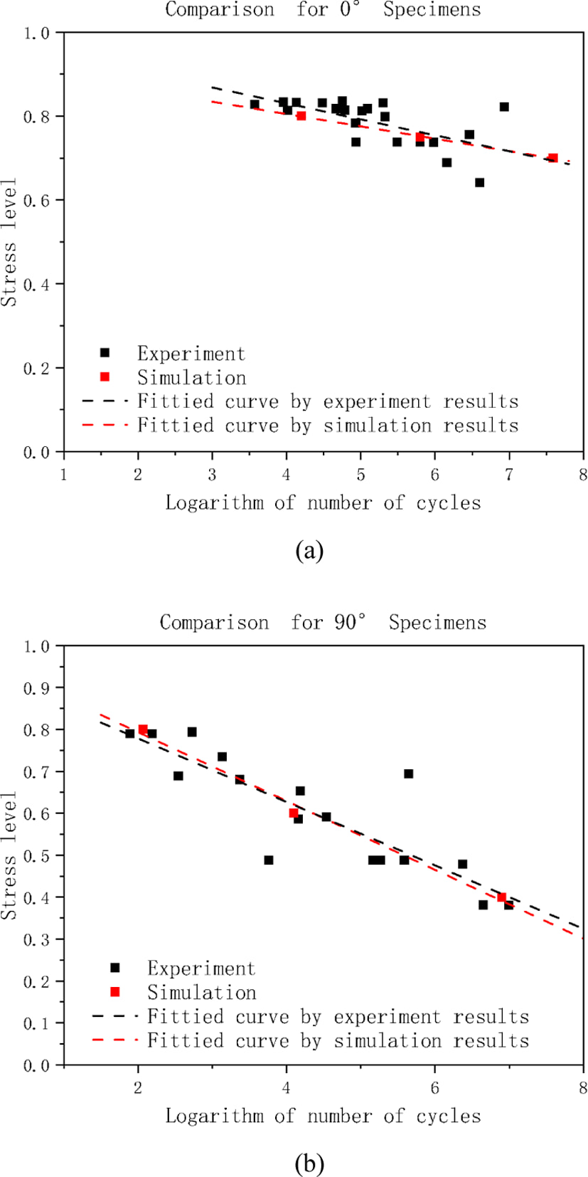
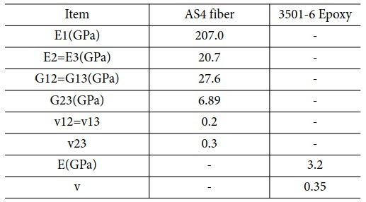
Material properties were adopted from the studies by Shokrieh and Liu and are presented in Tables 3 and 4 [16,21]. The UD lamina was assumed to be transversely isotropic, with identical material responses in the two transverse directions. Finite‐element analyses were performed using C3D8R elements. Fatigue simulations were carried out under tension–tension fatigue loading at a stress ratio of R = 0.1 on 0° specimens at 80%, 75%, and 70% of their static strength and on 90° specimens at 80%, 60%, and 40% levels. A sudden jump in displacement was taken as an indication of complete specimen failure and used to determine the fatigue life. Subsequently, the simulated S–N curve was plotted alongside the experimental S–N data[3] for comparison , as shown in Fig. 3. Fig. 3(a) presents the S–N curve comparison for the 0° specimens, while Fig. 3(b) shows the corresponding results for the 90° specimens.
The quantitative error metrics were calculated in the logarithmic fatigue life space because fatigue life usually spans several orders of magnitude. The prediction accuracy was mainly evaluated using MAElogN, which measures the average absolute deviation between the experimental and simulated fatigue lives in the logarithmic fatigue life space. In addition, RMSElogN was used as a supplementary indicator to reflect the influence of relatively large deviations. These error metrics are defined as follows:
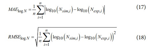
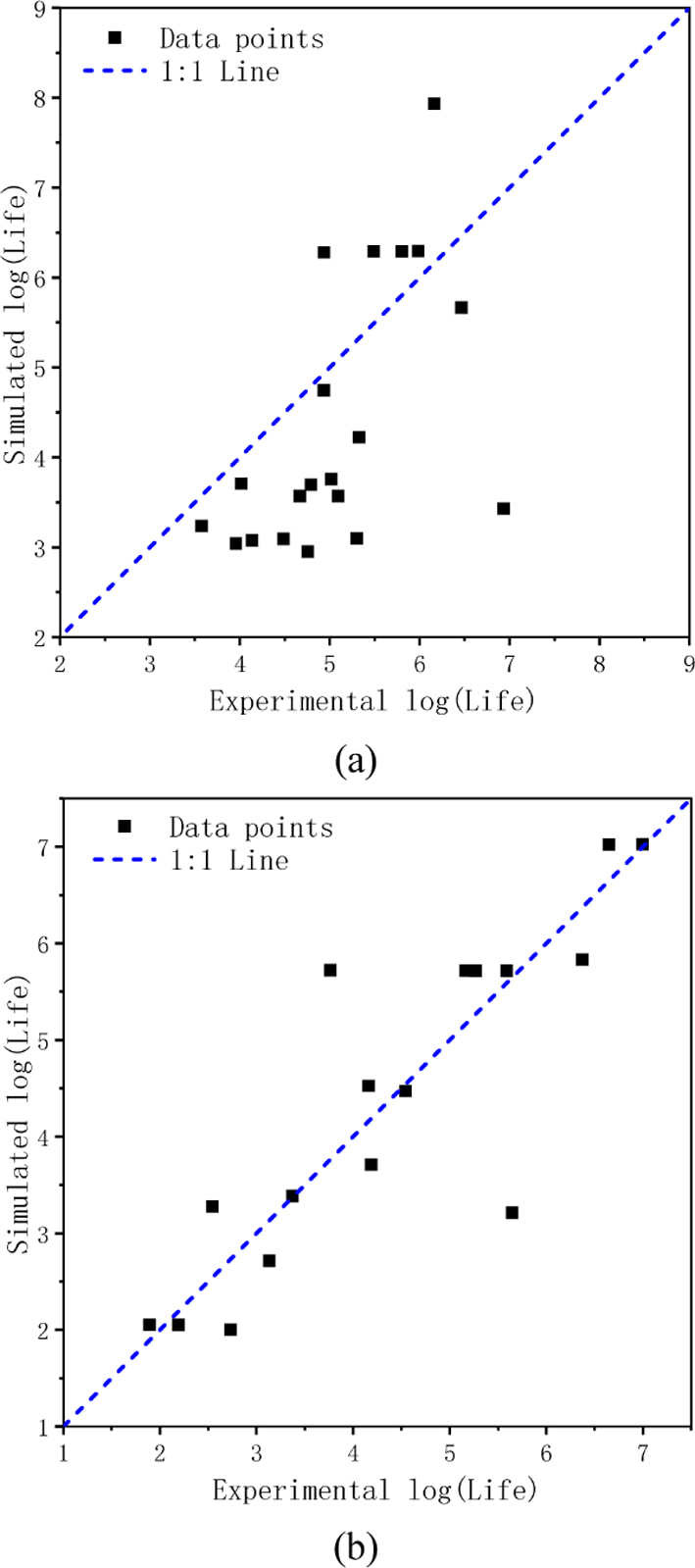
The prediction accuracy was quantified using MAElog N and RMSElog N in the logarithmic fatigue life space. These errors were calculated by comparing the fitted lines of the experimental and simulated S-N data at the same stress levels. The UD 0° data set showed relatively larger errors, with MAElog N = 0.597 and RMSElog N = 0.660, mainly because the experimental fatigue lives exhibited considerable scatter at identical stress levels, leading to a larger deviation between the fitted experimental and simulated S–N curves. However, the predicted fatigue lives still followed the overall experimental tendency. For the UD 90° data set, the errors were significantly reduced, with MAElog N = 0.125 and RMSElog N = 0.141, indicating better agreement between the predicted and experimental results. These results suggest that the simulation approach can reasonably capture the general fatigue life behavior of both UD 0° and UD 90° specimens, although the prediction accuracy depends on the fitted S-N response of each data set.
Fig. 4 presents a comparison between the predicted and experimental fatigue lives. For each experimental data point, the corresponding simulated fatigue life was obtained from the fitted S–N curve at the same stress level. The dashed 1:1 line represents perfect agreement between the experimental and predicted fatigue lives. The results show an overall correlation between the predictions and experiments, although relatively large deviations are observed for several data points, particularly for the 0° specimens. In comparison, the 90° specimens exhibit closer agreement with the 1:1 line.
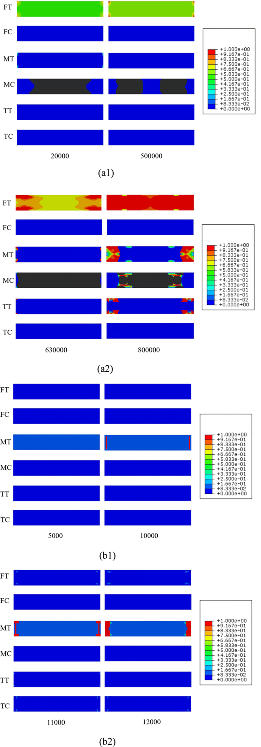
To further illustrate the progressive damage evolution predicted in the Abaqus simulations, Fig. 5 depicts the failure development of the specimens as a function of fatigue cycles based on the activation of different damage modes, including fiber tension (FT), fiber compression (FC), matrix tension (MT), matrix compression (MC), through-thickness tension (TT), and through-thickness compression (TC). The contour plots provide a clear visualization of the initiation and propagation of damage leading to final collapse, with the damage variables shown as contours indicating the extent of material damage; a value of 1 denotes failure. Specifically, Fig. 5(a1) and Fig. 5(a2) present the simulated progressive failure process of the 0° specimen subjected to a stress level of 75% of its static strength. In contrast, Fig. 5(b1) and Fig. 5(b2) show the corresponding damage evolution of the 90° specimen under a 60% stress level. These results highlight the distinct damage mechanisms and failure patterns associated with different loading directions and stress amplitudes.
|
Fig. 1 Fatigue analysis workflow via finite element analysis |
|
Fig. 2 Geometry and Dimensions of the Model Used in Finite Element Analysis |
|
Fig. 3 Comparison of simulated and experimental S–N curves: (a) 0° specimen and (b) 90° specimen |
|
Fig. 4 1:1 line comparison of experimental and predicted fatigue lives in the logarithmic scale: (a) 0° specimen and (b) 90° specimen |
|
Fig. 5 Simulated progressive failure processes: (a1)–(a2) 0° specimen from 20,000 to 800,000 cycles; (b1)–(b2) 90° specimen from 5,000 to 12,000 cycles |

This work establishes and validates a distinct multi-scale framework for predicting the fatigue behavior of resin based carbon-fiber composites. It embeds Mori-Tanaka micromechanics theory, the Hashin failure criterion, and Shokrieh and Lessard's stiffness and strength degradation laws, modified by Khan for transverse loading, into a single Abaqus/Standard UMAT. The subroutine is used with C3D8R elements: it updates the constituent moduli and strengths under cyclic loading, allowing damage evolution to be tracked throughout the loading history in finite element analysis.
In this framework, Mori–Tanaka mean-field homogenization provides a direct way to update effective material properties without relying on repeated finite element based homogenization. The effective ply properties can be updated analytically within the UMAT, reducing the need for repeated microscale computations during fatigue analysis. This supports efficient cycle-by-cycle stiffness and strength degradation modeling while retaining constituent level degradation information.
Fatigue simulations were performed on the unidirectional (UD) 0° specimen coupons at 80%, 75%, and 70% of their static strength, and on the unidirectional (UD) 90° specimens at 80%, 60%, and 40%, respectively. The results show that the predicted fatigue lives follow the experimental S-N trends for both UD 0° and UD 90° specimens. However, the validation in the present study is limited to a single material system and a specific set of UD specimen configurations. Therefore, further refinement and validation would be necessary to extend the present framework to off-axis specimens, multi-angle laminate configurations, and complex multiaxial fatigue loading conditions. Within the scope of the present validation, the proposed framework provides an efficient computational basis for the preliminary fatigue-life assessment of UD composite specimens under the loading conditions considered in this study.
Based on the present results and the UD coupon-level scope of the current study, further investigation is warranted for fatigue problems involving off-axis specimens, multi-angle laminate configurations. As an additional extension, the incorporation of interfacial damage mechanisms, such as fiber–matrix debonding, and environmental effects, could further improve the description of fatigue damage evolution beyond the current stiffness and strength degradation scheme.
This work was supported by the Institute of Engineering Research.
- 1. Kolasangiani, K., et al., “An experimentally validated 3D progressive fatigue damage model for fatigue life prediction of Flax-epoxy laminates,” Composites Part A: Applied Science and Manufacturing, Vol. 160, 2022, 107054.
-

- 2. Ghosh, G., Rudraprasad, B., and Dayakar, P., “Advances in multi-functional composite materials: applications and opportunities in automotive industry,” Functional Composites and Structures, Vol. 7, No. 4, 2025, 042001.
-
- 3. Ha, D., et al., “Multi-scale fatigue damage model for CFRP laminates considering the effect of progressive interface debonding,” Mechanics of Advanced Materials and Structures, Vol. 31, No. 11, 2024, pp. 2321-2333.
-
- 4. Kim, J.H., et al., “Multi-scale fatigue life prediction model for CFRP laminates considering the mechanical degradation of its constituents and the local stress concentration of the matrix,” Composite Structures, Vol. 349, 2024, 118519.
-
- 5. Senthilnathan, K., et al., “Microstructural damage dependent stiffness prediction of unidirectional CFRP composite under cyclic loading,” Composites Part A: Applied Science and Manufacturing, Vol. 100, 2017, pp. 118-127.
-
- 6. Ha, D., et al., “Multi-scale Progressive Fatigue Damage Model for Unidirectional Laminates with the Effect of Interfacial Debonding,” Composites Research, Vol. 36, No. 1, 2023, pp. 16-24.
-
- 7. Raja, T., et al., “High-performance epoxy composites reinforced with carbon fiber and bran filler: thermal integrity and fatigue resistance for load-bearing structures,” Functional Composites and Structures, Vol. 7, No. 4, 2025, 045007.
-
- 8. Hashin, Z., “Fatigue failure criteria for unidirectional fiber composites,” Journal of Applied Mechanics, Vol. 48, No. 4, 1981, pp. 846-852.
-
- 9. Hashin, Z., and Assa, R. “A fatigue failure criterion for fiber reinforced materials,” Journal of composite materials, Vol. 7, No. 4, 1973, pp. 448-464.
-
- 10. Shen, B., et al., “Progressive failure analysis of laminated CFRP composites under three‐point bending load,” Advances in Materials Science and Engineering, Vol. 2022, No. 1, 2022, 3047319.
-
- 11. Zhang, Y., Van Paepegem, W., and De Corte, W., “An Enhanced Progressive Damage Model for Laminated Fiber-Reinforced Composites Using the 3D Hashin Failure Criterion: A Multi-Level Analysis and Validation,” Materials, Vol. 17, No. 21, 2024, 5176.
-
- 12. Liu, P., et al., “Numerical analysis of bearing failure in countersunk composite joints using 3D explicit simulation method,” Composite Structures, Vol. 138, 2016, pp. 30-39.
-
- 13. Ju, J.W., and Chen, T.M., “Micromechanics and effective moduli of elastic composites containing randomly dispersed ellipsoidal inhomogeneities,” Acta Mechanica, Vol. 103, No. 1, 1994, pp. 103-121.
-
- 14. Mura, T., “Micromechanics of defects in solids,” Springer Science & Business Media, 2013.
- 15. Shokrieh, M.M., and Larry, B., “Progressive fatigue damage modeling of composite materials, Part I: Modeling,” Journal of Composite Materials, Vol. 34, No. 13, 2000, pp. 1056-1080.
-
- 16. Shokrieh, M.M., and Larry, B.L., “Progressive fatigue damage modeling of composite materials, Part II: Material characterization and model verification,” Journal of Composite Materials, Vol. 34, No. 13, 2000, pp. 1081-1116.
-
- 17. Khan, A.I., Satchi, V., and Ian, M., “Predicting fatigue damage of composites using strength degradation and cumulative damage model,” Journal of Composites Science, Vol. 2, No. 1, 2018, 9.
-
- 18. Tsai, S.W., and Edward, M.W., “A general theory of strength for anisotropic materials,” Journal of Composite Materials, Vol. 5, No. 1, 1971, pp. 58-80.
-
- 19. Chang, F.-K., and Chang, K.-Y., “A progressive damage model for laminated composites containing stress concentrations,” Journal of Composite Materials, Vol. 21, No. 9, 1987, pp. 834-855.
-
- 20. Puck, A., Kopp, J., and Knops, M., “Guidelines for the determination of the parameters in Puck’s action plane strength criterion,” Composites Science and Technology, Vol. 62, No. 3, 2002, pp. 371-378.
-
- 21. Liu, C., and Shi, Y., “An improved analytical solution for process-induced residual stresses and deformations in flat composite laminates considering thermo-viscoelastic effects,” Materials, Vol. 11, No. 12, 2018, 2506.
-
- 22. Adam, T., et al., “Fatigue life prediction for hybrid composites,” International Journal of Fatigue, Vol. 11, No. 4, 1989, pp. 233-237.
-
 This Article
-
2026; 39(4): 296-303
Published on Aug 31, 2026
- 10.7234/composres.10.7234/composres.2026.39.4.296
- Received on May 28, 2026
- Revised on Jun 22, 2026
- Accepted on Jul 25, 2026
Services
- Abstract
1. introduction
2. multi-scale fatigue model
3. simulation
4. conclusions
- Acknowledgements
- References
- Full Text PDF
Shared
Correspondence to
- Gun Jin Yun
-
Department of Aerospace Engineering, Seoul National University, Institute of Advanced Aerospace Technology, Seoul National University
- E-mail: gunjin.yun@snu.ac.kr
 Copyright ⓒ The Korean Society for Composite Materials. All rights reserved.
Gangnam Mirae Tower, Suite 601, 174 Saimdang-ro, Seocho-gu, Seoul 06627, South Korea
Tel: +82-2-598-1550 Fax: +82-2-598-1557 E-mail: composites@kscm.re.kr