


- Research Trends on Key Components of Proton Exchange Membrane Fuel Cells (PEMFC): A Review
Seung-Cheol Shin*# , Myungjin Hong*# , Eun Ju Jeong*, Seong Jun Kim*, Seung Woo Choi*, Hyun Tak Kim*, Tak Heo*, Min Jeong Kim*, Young Kyu Kim*, Sang Eui Lee*†
* Department of Mechanical Engineering, Inha University, Incheon 22212, Republic of Korea
This article is an open access article distributed under the terms of the Creative Commons Attribution Non-Commercial License (http://creativecommons.org/licenses/by-nc/4.0) which permits unrestricted non-commercial use, distribution, and reproduction in any medium, provided the original work is properly cited.
As the need for alternative energy increases due to the depletion of fossil fuels, environmental problems and the increase in electricity demand, alternatives are being sought. Hydrogen energy and fuel cell technologies are attracting more attention due to their pollution-free and high efficiency. Proton exchange membrane fuel cells, which use hydrogen as fuel, are mainly used in vehicles, portable devices, and various applications, and are emerging as next-generation technologies that can solve environmental problems due to little pollutant emissions. This paper explained about the operating principles of fuel cells, types of fuel cells, and market trends, and especially analyzed and summarized the research trend related to 1) GDBL(gas diffusion backing layer), 2) MPL(micro porous layer), 3) BP(bipolar plate) 4) MEA(membrane electrode assembly) which are key parts of PEMFC(proton exchange membrane fuel cell).
Keywords: Gas diffusion backing layer(GDBL), Micro porous layer(MPL), Bipolar plate(BP), Membrane electrode assembly (MEA)
In the 21st century, the global community is facing the dual challenges of fossil fuel depletion and environmental pollution. In particular, the energy consumption of underdeveloped countries has surged due to rapid economic development. According to forecasts, if the per capita energy consumption in underdeveloped countries reaches half the level of OECD member states, global oil consumption will need to increase to more than seven times the combined current consumption levels of the United States and Europe [1].
The International Energy Agency (IEA) estimated in 1986 that the reserve life of fossil fuels is approximately 34 years for oil, 57 years for natural gas, 174 years for coal, and 58 years for uranium. Assuming a 1.6% annual increase in energy consumption—similar to the trend over the past decade—major fossil fuels will be depleted within the next 70 years. This depletion is expected to be accelerated by population growth and increasing energy demands of developing countries [2].
According to the IEA’s World Energy Outlook for 2020-2040, coal demand has not returned to pre-COVID-19 levels, and the era of increasing oil demand will end within 10 years. Natural gas is currently experiencing short-term oversupply and is forecast to have a relatively stable outlook compared to other fossil fuels. But the demand for these fossil fuels remains highly sensitive to policy and economic factors. Although global energy demand was initially expected to grow by 12% between 2019 and 2030, the COVID-19 pandemic temporarily slowed this growth. Nevertheless, the IEA projects that fossil fuel demand will rebound as economies recover and existing energy policies are maintained [3]. As a result, fossil fuel depletion is also expected to accelerate alongside the resurgence in energy consumption.
Among the environmental issues caused by fossil fuels, global warming has attracted significant attention. The combustion of fossil fuels—mainly composed of carbon compounds—releases carbon dioxide (CO₂), a major greenhouse gas. The excessive use of fossil fuels has led to increased atmospheric CO₂ concentrations, resulting in climate change, sea level rise, and other environmental challenges. Notably, the majority of anthropogenic greenhouse gas emissions originate from fossil fuel combustion processes [4]. Consequently, the need for alternative energy sources has become increasingly urgent.
To transition from a fossil fuel-based economy to a hydrogen-based energy system, various governments and institutions are actively pursuing hydrogen energy development strategies. Research is being conducted on multiple hydrogen production technologies, along with the development of hydrogen-based power generation systems such as fuel cells, combustors, gas turbines, and internal combustion engines. Although these technologies are still in the early stages of development, efforts are ongoing to secure fundamental technologies and expand related infrastructure. Since the 2010s, competitiveness in the hydrogen energy market and the availability of hydrogen-based products have steadily improved. Hydrogen energy not only contributes to reducing global warming and environmental pollution, but also poses no risk of resource depletion [5].
In 2019, the Korean government announced a hydrogen economy revitalization roadmap aimed at utilizing hydrogen as a key energy source and creating new employment opportunities [6]. In addition, countries around the world are implementing policies to promote hydrogen energy as part of their carbon reduction strategies. Unlike hydrogen, renewable energy sources such as solar, wind, and hydropower exhibit fluctuating outputs due to environmental factors, necessitating efficient energy storage solutions [7].
Fuel cell technology, which converts chemical energy into electricity, plays a central role in the hydrogen economy. Fuel cells are categorized by characteristics such as power density, operating temperature, and electrolyte type, and are generally classified into portable, transportation, and stationary applications. Furthermore, because large-scale infrastructure such as thermal or nuclear power plants is unnecessary, electricity can be generated on-site, tailored to specific energy demands. With applications ranging from personal portable devices to residential power systems, fuel cells represent a promising core technology for the future energy landscape [8].
In this paper, various types of fuel cells are reviewed, with a particular focus on the characteristics, research trends, and market developments of proton exchange membrane fuel cell (PEMFC) both domestically and internationally.
2.1 Principle of fuel cell
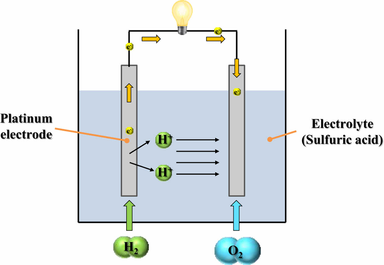
In general, a fuel cell is an energy conversion device that directly transforms the chemical energy of fuel into electrical energy and heat. It is composed of two electrodes, an anode and a cathode, and an electrolyte. Hydrogen is continuously supplied to the anode, while oxygen (typically from air) is supplied to the cathode. At the anode, a catalytic oxidation reaction occurs, decomposing hydrogen molecules into protons (H+) and electrons (e-). The electrolyte selectively allows only protons to pass through to the cathode, while acting as an electronic insulator.
Protons reaching the cathode react with oxygen and incoming electrons from the external circuit, resulting in the formation of water. This electrochemical reaction generates an electric current via the movement of electrons through the external circuit. The simplest form of a fuel cell that uses sulfuric acid as the electrolyte is shown in Fig. 1.
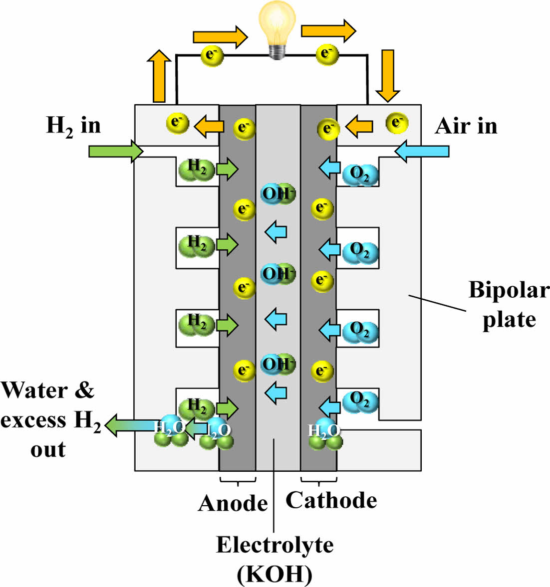
In addition to fuel cells that use cation-conducting electrolytes, there are also those that utilize anion-conducting electrolytes, in which hydroxide ions (OH-) serve as the charge carriers. In these systems, oxygen undergoes reduction at the cathode via a catalyst, generating hydroxide ions. Upon reaching the anode via the electrolyte, the ions react with hydrogen, producing water and emitting electrons. Although the ions move in the reverse direction compared to fuel cells that use cation-conducting electrolytes, both systems rely on the same basic mechanism—electrochemical redox reactions that convert chemical energy into electricity [9].
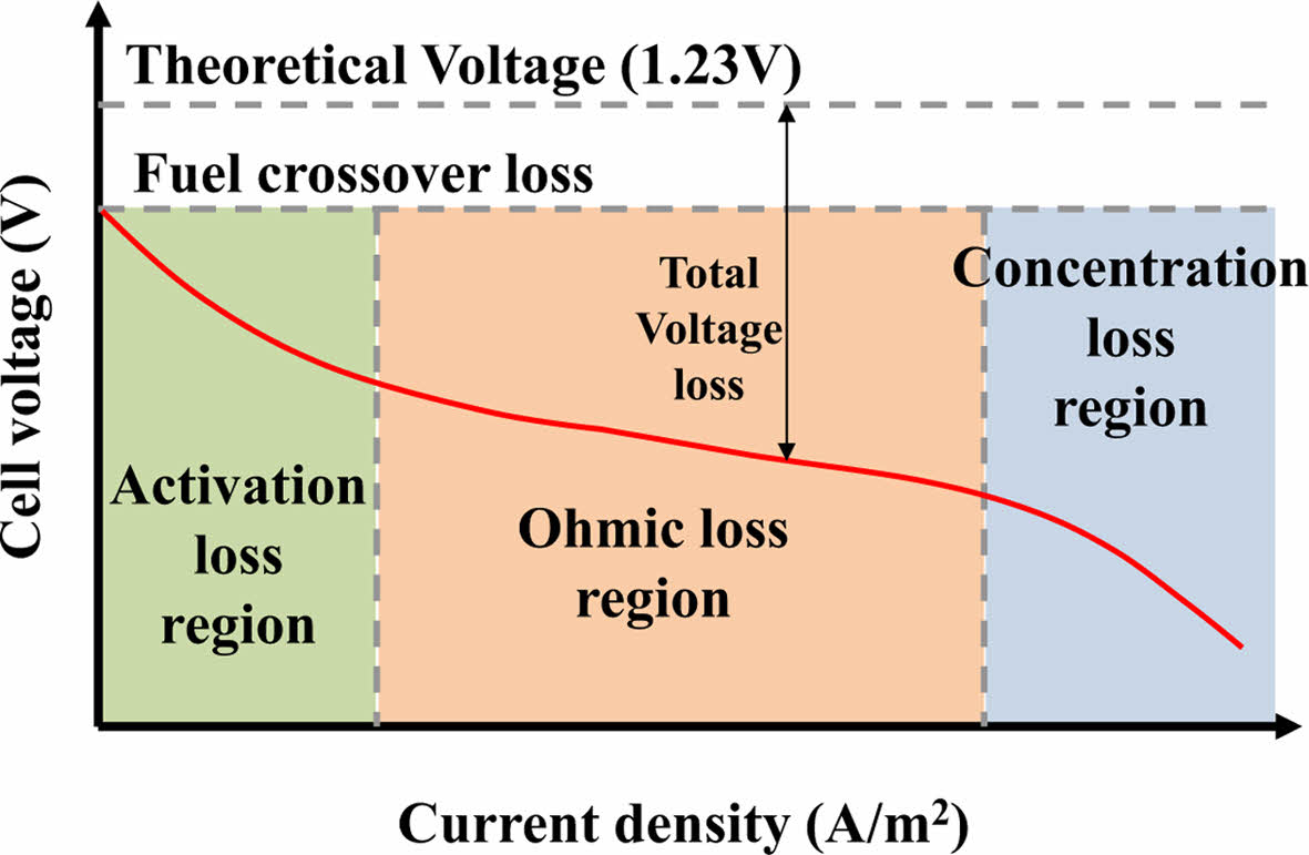
The open-circuit voltage of a single fuel cell is typically around 1.23 V under ideal conditions. However, due to practical voltage losses and the low output of individual cells, multiple cells are generally stacked in series and parallel configurations to achieve usable power levels. The characteristic voltage-current behavior of a fuel cell is represented by a polarization curve, as illustrated in Fig. 2.
As current density increases, the output voltage drops due to various internal losses. These losses are categorized into three major current density regions:
Activation loss: At low current densities, this region is primarily influenced by the slow rate of the electrochemical reactions, particularly at the electrode-electrolyte interface.
Ohmic loss: At intermediate current densities, the main cause of voltage drop is the resistance associated with ion transport through the electrolyte and electron flow through the electrodes and interconnects.
Concentration loss: At high current densities, mass transport limitations reduce the effective supply of reactants to the catalyst sites, often leading to flooding in the gas diffusion layer, especially under high humidity conditions.
The overall performance of a fuel cell system depends on both thermodynamic and electrical efficiency. Thermodynamic efficiency is influenced by factors such as fuel utilization, water management, and thermal control, while electrical efficiency is affected by various internal losses, including activation, ohmic, and concentration losses [10].
2.2 Types of fuel cells
Fuel cells are typically categorized according to the nature of the fuel and the electrolyte employed. The major types include:
1) Proton Exchange Membrane Fuel Cell (PEMFC), 2) Direct Methanol Fuel Cell (DMFC), 3) Direct Ethanol Fuel Cell (DEFC), 4) Solid Oxide Fuel Cell (SOFC), 5) Phosphoric Acid Fuel Cell (PAFC), 6) Molten Carbonate Fuel Cell (MCFC), 7) Alkaline Fuel Cell (AFC), etc.
Among these, PEMFC, DMFC, DEFC, PAFC, and AFC are classified as low-temperature fuel cells, which operate below 250°C. These systems are characterized by fast catalytic activity and relatively high power output. However, since they typically use noble metal catalysts such as platinum, their performance is highly sensitive to fuel impurities. In addition, the high cost of the catalyst contributes to the overall cost of the system, which is a major disadvantage.
Fuel cells such as MCFC and SOFC fall under the category of high-temperature systems due to their elevated operational ranges, typically functioning at temperatures above 500°C, and have the advantage of using a metal catalyst such as nickel. But because it operates at a high temperature, the durability problem of peripheral parts due to heat is emerging as a disadvantage.
2.2.1 PEMFC (Proton Exchange Membrane Fuel Cell)
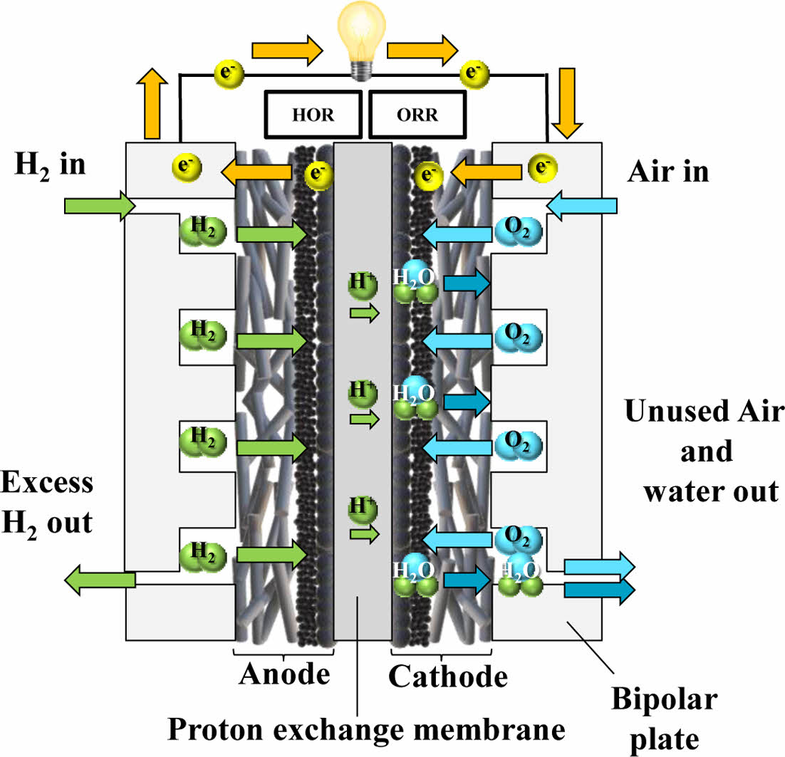
PEMFC is an electrochemical system that produces electrical power through a redox reaction between hydrogen and oxygen. Compared to other energy conversion systems, PEMFC is advantageous in terms of ease of maintenance, fast start-up time, and high energy conversion efficiency. They are also lightweight, have low noise levels, and exhibit high power density. With an operating temperature typically ranging from 80°C to 200°C, PEMFC is widely applied in diverse sectors, including transportation, power generation, and portable electronics.
A single PEMFC unit (or cell) consists of an anode, cathode, electrolyte membrane, gas diffusion layer, and catalyst layers. Multiple single cells are connected in series to form a stack, which is sealed by end plates. At the anode, hydrogen gas is introduced, whereas oxygen or air is delivered to the cathode. The platinum catalyst at the anode promotes the dissociation of hydrogen into protons and electrons [11]. The protons traverse the proton exchange membrane toward the cathode, where they combine with electrons and oxygen to form water.
Since water is the only byproduct of the electrochemical reaction, PEMFC is considered a viable and eco-friendly substitute for traditional fossil fuel-driven energy conversion technologies, as illustrated in Fig. 3. Furthermore, because the reaction is not limited by the Carnot efficiency, PEMFC exhibits higher energy conversion efficiencies than conventional internal combustion engines. Nonetheless, issues related to durability and stability remain, largely attributed to the high cost of platinum catalysts and operational issues such as water management, oxygen supply, and susceptibility to contaminants [12].
One of the critical elements in PEMFC is the proton-conducting membrane, which permits the transport of H+ but inhibits the flow of electrons. Hydrogen ions migrate across the proton-conducting membrane to reach the cathode, while the electrons are directed through an outer electrical pathway, producing electric power.
Due to differences in water concentration, pressure, and proton migration, water transport can occur in both directions across the membrane, influencing cell performance and water management strategies [13].
2.2.2 DMFC (Direct Methanol Fuel Cell)
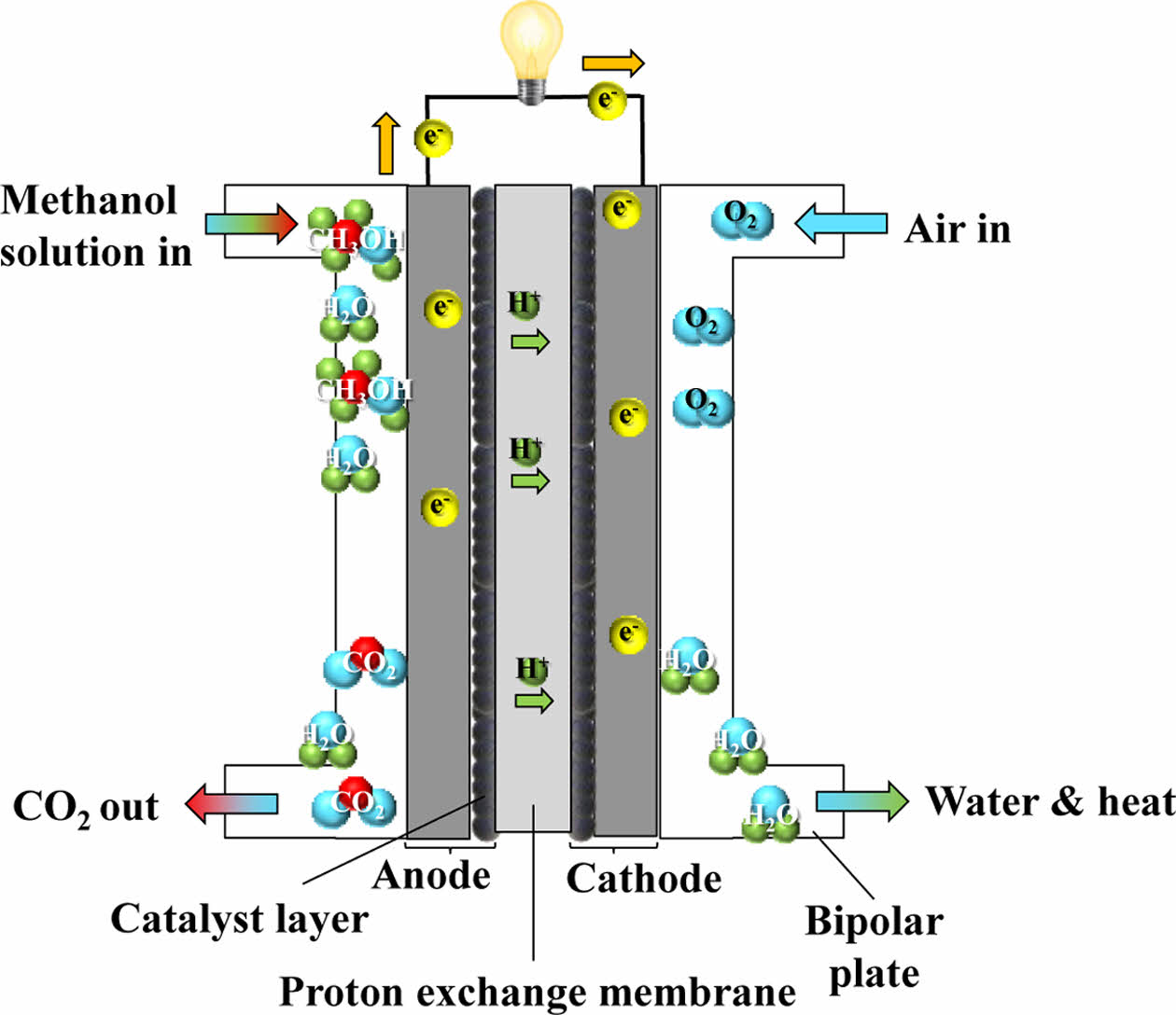
DMFC shares a similar operating mechanism with the PEMFC, but differs in that it uses liquid methanol directly as a fuel instead of hydrogen. As methanol can be supplied in liquid form to the anode without the need for external reforming or hydrogen storage, the fuel supply system can be simplified and miniaturized. This characteristic makes DMFC particularly attractive for portable applications. However, the oxidation of methanol requires a higher loading of platinum catalysts, which increases cost, and the low catalytic activity results in lower power density compared to hydrogen fuel cells [14]. The schematic diagram of DMFC is illustrated in Fig. 4.
Since DMFC does not require bulky hydrogen tanks or reformers, the system can be downsized for integration into portable electronic devices. Furthermore, the power density of DMFC is approximately three times that of lithium-ion secondary batteries, offering longer operation times and convenient refueling [15].
Despite these advantages, two major challenges remain before DMFC can be fully commercialized. The first issue is durability. After 200 hours of operation, significant performance degradation has been observed, which becomes more severe beyond 1,000 hours of continuous use [16]. The second issue relates to thermal management. The heat-releasing reaction of methanol with oxygen increases the system’s internal temperature, which increases water vapor pressure in the cathode. This thermal effect can drive water crossover from the anode to the cathode, thereby reducing hydrogen ion availability and degrading performance [17].
2.2.3 DEFC (Direct Ethanol Fuel Cell)
Due to the difficulties associated with storing and distributing gaseous hydrogen, interest has grown in fuel cells that directly utilize liquid fuels. One such system is DEFC, which uses ethanol as its primary fuel. DEFC shares the same fundamental structure as PEMFC [18], but the oxidation of ethanol proceeds through more complex electrochemical pathways that are commonly referred to as the C1 and C2 pathways, resulting in slower reaction kinetics.
In the C1 pathway, the carbon-carbon bond of ethanol is broken, leading to the production of intermediates such as CO or CHx species. Further oxidation of these intermediates results in CO₂, H₂O, and the release of electrons. In contrast, the C2 pathway proceeds without breaking the C-C bond, producing partially oxidized compounds such as acetaldehyde and acetic acid, along with water and electrons.
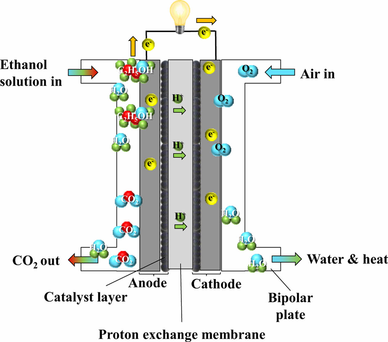
Due to the complexity and sluggishness of ethanol oxidation, DEFC generally requires elevated operating temperatures (≥100°C) to achieve acceptable performance, necessitating the use of membranes different from those used in conventional PEMFC. Ethanol has a higher theoretical energy density than hydrogen and offers practical advantages such as ease of handling and storage. Moreover, ethanol can be sustainably produced via fermentation of biomass sources such as sugarcane and corn, offering environmental benefits by reducing emissions of CO, CO₂, and hydrocarbons. Ethanol is considered safe for use and cost-effective, positioning DEFC as a viable option for future fuel cell technologies [19]. The schematic diagram of DEFC is illustrated in Fig. 5.
2.2.4 SOFC (Solid Oxide Fuel Cell)
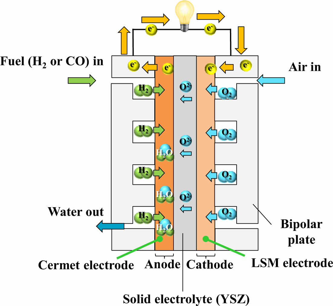
SOFC is a type of fuel cell that functions at elevated temperatures, generally between 600°C and 1000°C, enabling high energy conversion efficiency. Unlike low-temperature fuel cells, SOFC does not require noble metal catalysts such as platinum and instead utilize inexpensive metal components, thus reducing material costs. However, the high operating temperature poses challenges in terms of system reliability and material stability [20].
SOFC uses a solid ceramic electrolyte, typically yttria-stabilized zirconia, which provides the mechanical strength and thermal stability necessary for long-term operation at elevated temperatures [21]. A notable advantage of SOFC is their fuel flexibility—they can utilize not only hydrogen but also hydrocarbon-based fuels such as natural gas, allowing integration into existing fossil fuel infrastructure [8]. The schematic diagram of SOFC is illustrated in Fig. 6.
2.2.5 PAFC (Phosphoric Acid Fuel Cell)
PAFC is one of the most mature and technically manageable fuel cell types. Having been commercialized since the 1970s, it has been widely adopted in stationary power generation, particularly for combined heat and power applications. Hundreds of PAFC systems have been deployed globally to supply both electricity and thermal energy for buildings and local infrastructure.
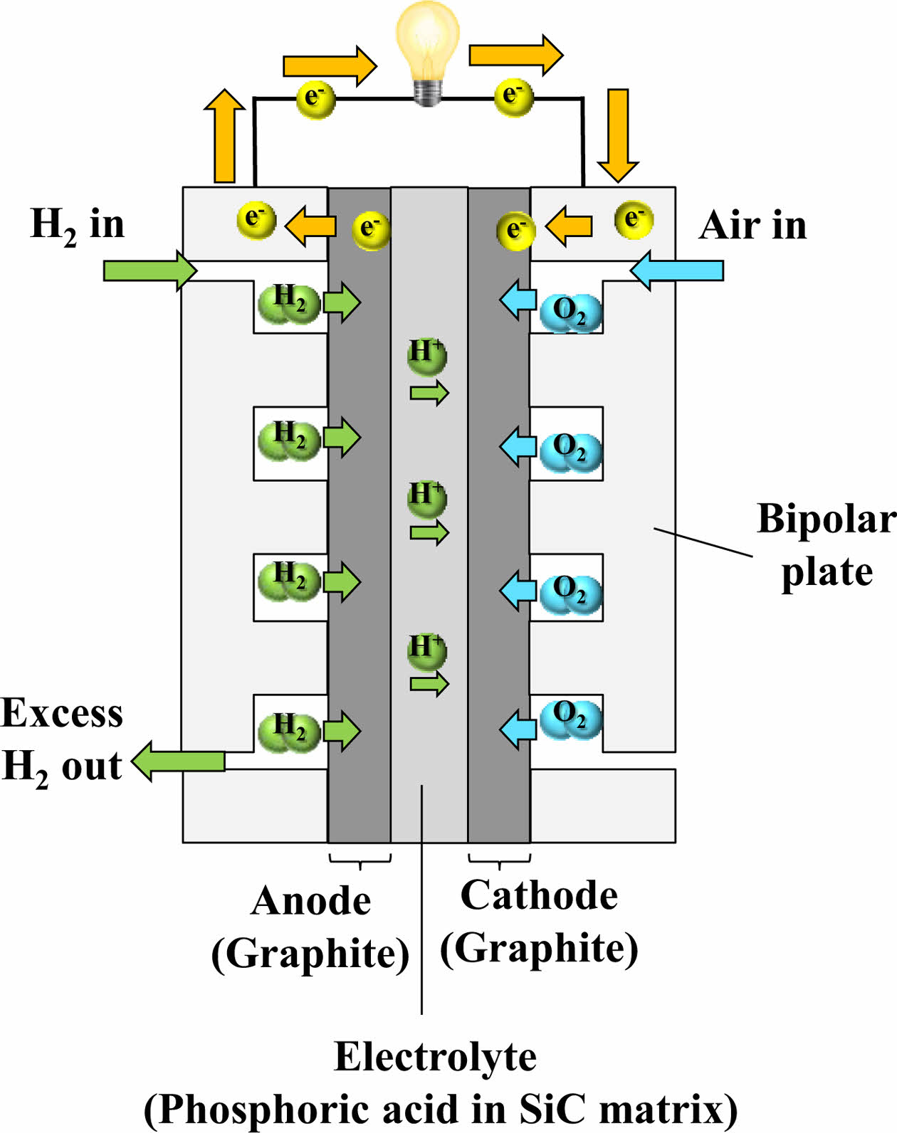
PAFC exhibits high reliability, with a mean time before failure ranging from approximately 2,500 to 6,750 hours, and a net power generation efficiency of around 37% [22]. In this system, at the anode, hydrogen undergoes oxidation to generate hydrogen ions, whereas at the cathode, atmospheric oxygen combines with these ions and electrons to yield water. Liquid phosphoric acid (H₃PO₄) is used as the electrolyte, retained in a porous SiC support structure, which simultaneously serves as a separator. This structure prevents electrode short-circuiting and gas crossover while providing mechanical integrity [21]. The schematic diagram of PAFC is illustrated in Fig. 7.
2.2.6 MCFC (Molten Carbonate Fuel Cell)
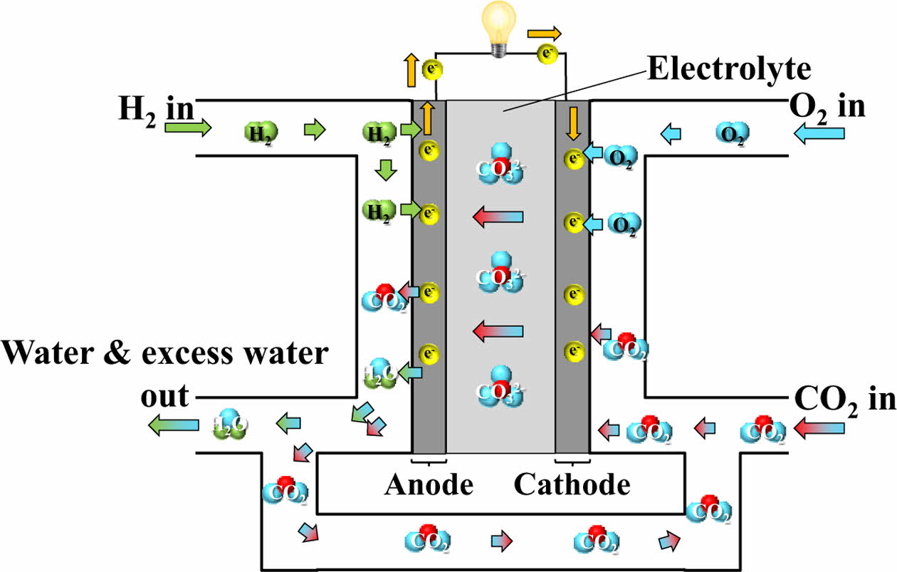
MCFC typically functions at around 650°C to maintain adequate ion transport within the electrolyte. Due to this elevated operating temperature, MCFC is particularly suitable for large-scale energy applications, including centralized power generation facilities and integrated heat and power systems [23].
The elevated operational temperature permits the utilization of economically viable catalysts such as nickel, thereby removing the dependency on precious metals. MCFC generally consists of a porous anode made primarily of nickel (Ni), a porous cathode composed of nickel oxide (NiO), and a porous matrix of lithium aluminate (LiAlO₂) that contains a mixed molten carbonate electrolyte. Additionally, separators are used to isolate the fuel gas at the anode from the oxidant gas at the cathode, guide the flow of process gases, and serve as current collectors [24]. In addition, MCFC exhibits higher fuel utilization efficiency than PAFC for the same electrode area, which enables more compact and cost-effective system designs [25]. The schematic diagram of MCFC is illustrated in Fig. 8.
2.2.7 AFC (Alkaline Fuel Cell)
AFC is the first fuel cell type to be commercialized in the early 20th century, enabling efficient electricity generation from hydrogen [26]. AFC employs an aqueous potassium hydroxide (KOH) solution as its electrolyte, which requires the supply of hydrogen and oxygen in high purity. Exposure to carbon dioxide leads to the formation of potassium carbonate, which degrades performance and blocks ion conduction.
In AFC, hydroxide ions (OH-) serve as the charge carriers, migrating from the cathode to the anode, opposite to the proton (H+) transport direction in PEMFC. To address limitations related to liquid electrolytes, such as CO₂ poisoning and leakage, a newer electrolyte type known as the Anion Exchange Membrane (AEM) has been developed. While AEM offers improved handling and system integrity, its ionic conductivity and chemical stability still fall short of those observed in PEMFC [27].
AFC operates in a moderate temperature range (60°C to 220°C) and offers low manufacturing costs, making it a subject of ongoing research for cost-effective energy solutions. The schematic diagram of AFC is illustrated in Fig. 9.
2.3 Market conditions of fuel cell
2.3.1 Domestic market conditions
The depletion of fossil fuels, long the main source of industrial energy, and the excessive emission of carbon dioxide have led to global warming concerns [28]. In response, many developed countries have declared carbon neutrality policies aimed at achieving net-zero carbon emissions [29]. South Korea has also aligned itself with this trend by strengthening technological development and R&D support under the "2050 Carbon Neutral" initiative [30]. As part of this effort, the government announced the "Hydrogen Economy Revitalization Roadmap" with the goal of establishing a hydrogen-based industrial ecosystem, building related infrastructure, and securing core energy technologies by 2040 [28].
To gain an early lead in the global fuel cell market, major Korean conglomerates, including SK, POSCO, Hyundai Motor, Hanwha, and Hyosung, invested a combined total of 43 trillion KRW in 2021. Additionally, the Hydrogen Portfolio Standards policy was separated from the existing Renewable Portfolio Standards to further promote fuel cell adoption [31].
The domestic supply of fuel cells increased significantly from 193,369 toe in 2014 to 313,303 toe in 2017. That year, fuel cell-based power generation accounted for 32% of the total renewable energy generation (46,623 GWh), and both domestic production and cumulative supply capacity have shown continuous growth [8]. The Korean fuel cell market was valued at approximately $300 million in 2015 and is expected to grow at an average annual rate of 41%, reaching around $3.7 billion by 2022 [32]. The market value, which was 2.2 trillion KRW in 2018, is projected to grow at an annual rate of 30%, reaching approximately 50 trillion KRW by 2030 [7].
In the transportation sector, PEMFC accounts for over 99% of the total market. As demand for hydrogen-electric vehicles increases, the PEMFC market is expected to expand further [33]. As of September 2020, a total of 9,494 hydrogen-electric vehicles, including passenger cars and buses, were registered in Korea. This is a significant increase from the 29 vehicles registered in 2015, largely driven by the government’s aggressive policy implementation. In the "Green Mobility" initiative under the Korean New Deal announced in 2020, the government set a goal of supplying 200,000 hydrogen-electric vehicles by 2025 [34].
The government and major corporations are making large-scale investments in hydrogen fuel cell vehicles to gain early market dominance. Hyundai Motor Company has led the global hydrogen vehicle market with the “Nexo,” a PEMFC-based hydrogen car, and is extending fuel cell applications to drones, ships, military vehicles, and trains [8]. Hyundai’s hydrogen-powered truck “Xcient” was exported to Switzerland and North America in 2020, with approximately 1,600 additional units planned for delivery by 2025. Hyundai Rotem is also developing hydrogen trams and trains, with Ulsan city planning to launch commercial operations of these trams starting in 2027 [7].
Gas diffusion layer (GDL), one of the core components of hydrogen fuel cells, is currently produced by companies such as SGL and Toray and is entirely imported into Korea. However, domestic companies are working to localize production. Envioneer, a Korean advanced materials company, is developing GDL using a wet carbon fiber process [35]. In 2012, JNTG became the first Korean company to develop roll-type GDL and has been collaborating with Hyundai Motor Company and Seoul National University for over a decade.
Bipolar plates are produced by Sejong Industrial, Hyundai Steel, and POSCO. Hyundai Steel produces and sells more than 3,000 tons of hydrogen annually by Coke Oven Gas, and produces metal bipolar plates and supplies them to Hyundai Mobis. The production capacity was expanded from 16,000 units in 2019 to 46,000 units in 2022 - an increase of 2.9 times.
Electrolyte membranes, which were previously monopolized by Gore (USA), have been successfully localized by Sang-A Frontec after five years of development. Sang-A Frontec’s entry into the PEM supply chain represents a major breakthrough, given the high technical barriers of the membrane industry. This development is expected to significantly enhance the growth potential of Korea’s hydrogen-electric vehicle industry.
By February 2020, a total of 80 hydrogen refueling stations were planned, of which Hyosung Heavy Industries accounted for 22 (27.5%), Kwangshin Machinery for 14 (17.5%), and Nel Korea for 13 (16.3%). Since the announcement of the hydrogen economy roadmap in 2019, the construction of hydrogen refueling infrastructure has accelerated. Given the superior competitiveness of hydrogen vehicles, especially for medium- and large-sized applications, rapid adoption is expected in sectors such as public transportation and smart city development [36].
2.3.2 International market conditions
The global fuel cell market is projected to grow at an average annual rate of 25.86%, increasing from 789.79 MW in 2018 to 2,494.58 MW by 2023. Among various types, PEMFCs are expected to experience a growth rate of approximately 26.89% during the same period, expanding from 548.46 MW to 1,844.4 MW [37].
Fuel cell policies have been actively implemented in many countries. Notable examples include the Self-Generation Incentive Program in California, USA, and the Ene-Farm program in Japan. The United States has supported fuel cell deployment through SGIP, while Japan has promoted residential fuel cell adoption through Ene-Farm and set a goal of supplying 5.3 million fuel cells by 2030. Such initiatives reflect the growing global recognition of fuel cells as a core component of future energy systems [8].
As of 2015, PEMFC held the largest share of the global fuel cell market at 68.2%, followed by PAFCs at 11.3%, MCFC at 9.5%, SOFC at 8.0%, and other types at 3.0% [11]. By 2025, the market shares of PEMFC, PAFC, SOFC, and MCFC are expected to increase to 37.3%, 37.9%, 39.0%, and 38.2%, respectively [8].
In 2019, Bloom Energy held the largest global market share for power generation fuel cells at 50.1%, followed by Doosan Fuel Cell (33.6%) and Fuel Cell Energy (13.8%). In the residential and commercial building sector, Japanese companies led the market, with Panasonic and Aisin Seiki accounting for 45.2% and 44.3%, respectively. Korea, Japan, and the United States dominate the hydrogen electric vehicle market, with Hyundai Motor Company at 60.5% and Toyota at 33.7%. In the MCFC sector, FuelCell Energy has secured a strong position based on proprietary technology. Bloom Energy, a major player in SOFC, has sold over 350 MW of fuel cells in the U.S. and continues to engage in various international collaborations. In September 2018, it launched the FCgen-LCS platform - a large-scale liquid-cooled stack designed to improve power output, durability, and cold-start capability while reducing cost [38].
In Korea, PAFC and MCFC systems currently dominate the power generation fuel cell market, with companies such as Doosan Fuel Cell, Korea Fuel Cell, and Bloom SK Fuel Cell leading the industry [31]. Japan has secured the second-largest share in the hydrogen vehicle market, partly through the deployment of residential fuel cells. China, although currently limited in terms of complete fuel cell systems, is home to many materials and component manufacturers and is expected to expand its presence in the market through active industrial collaboration [29].
Hydrogen fuel cell vehicles began small-scale production in 2015 and are expected to achieve a market share of 25.9% across North America, Western Europe, and the Asia-Pacific region, with a total market size of approximately 123 trillion KRW by 2030. The fuel cell automotive parts market is also expected to continue growing, reaching 400 billion KRW, compared to its size in 2007 [39].
PEMFC, particularly in the transportation sector, is the most widely applied type of fuel cell across mobility platforms. Notable applications include Hyundai Motor’s “Nexo” and Toyota’s “Mirai,” which represent key models in the hydrogen vehicle market. In the United States, hydrogen fuel cell forklifts are operated in logistics centers of companies such as Walmart and Amazon, with more than 20,000 units in use [7]. While Korea and Japan lead the hydrogen vehicle market, China has been producing over 2,000 hydrogen-powered trucks and buses annually. Pilot projects for medium- and large-sized hydrogen commercial vehicles are also ongoing in the United States, Japan, and China [40].
Perfluorosulfonic acid (PFSA), a key component of the fluorine-based reinforced membranes in hydrogen fuel cells, is produced by global chemical companies such as 3M, Dow, Solvay, and Asahi Kasei E-Materials. Among them, Dupont’s Nafion membranes are the most widely used in PEMFC applications. While Nafion exhibits excellent chemical stability and mechanical durability, it suffers from decreased performance under low humidity and high temperature conditions, and it remains costly [41-43]. Nafion currently holds a market share of approximately 70% within the PFSA membrane sector [27].
The membrane industry for automotive fuel cells is considered high value-added, and fluorinated expanded polytetrafluoroethylene materials developed by Gore are used in most membrane electrode assembly (MEA). Although Korea’s Sang-A Frontec has recently succeeded in developing e-PTFE membranes, Gore continues to dominate the global market.
Governments and companies in Korea, the United States, China, and the European Union are actively promoting hydrogen mobility and investing in fuel cell R&D. However, the widespread adoption of hydrogen fuel cell vehicles remains constrained by high development costs and limited hydrogen refueling infrastructure. The COVID-19 pandemic also temporarily affected the market, leading to factory shutdowns and reduced sales. Nonetheless, Hyundai Motor Company’s flagship model, Nexo, experienced a 61% increase in global sales compared to 2019. Its global market share rose from 44.3% in 2019 to 73.8% in 2020, highlighting its rapid growth potential [40].
|
Fig. 1 Schematic diagram of the simplest form of a fuel cell |
|
Fig. 2 Various types of losses that occur during fuel cell operation |
|
Fig. 3 Schematic diagram of PEMFC |
|
Fig. 4 Schematic diagram of DMFC |
|
Fig. 5 Schematic diagram of DEFC |
|
Fig. 6 Schematic diagram of SOFC |
|
Fig. 7 Schematic diagram of PAFC |
|
Fig. 8 Schematic diagram of MCFC |
|
Fig. 9 Schematic diagram of AFC |
The key components of PEMFC can be categorized into four parts:
1. Gas Diffusion Backing Layer (GDBL),
2. Micro Porous Layer (MPL),
3. Bipolar Plate (BP),
4. Membrane Electrode Assembly (MEA).
Recent studies have focused intensively on the development and performance improvement of these core materials.
3.1 Gas diffusion backing layer (GDBL) research trends
GDBL in PEMFC plays a critical role in uniformly distributing reactant gases, conducting generated electrons and heat, and facilitating the removal of produced water. Typically composed of carbon paper, the GDBL serves as the structural substrate of the gas diffusion layer (GDL). To enhance electron and heat transfer, gas transport, and water management, recent studies have focused on improving the GDBL's porosity, wettability, electrical conductivity, and thermal conductivity through material selection and structural optimization.
Shanguan et al. conducted a numerical study to investigate liquid water transport depending on the porosity distribution in MPL-less GDBL. Five GDBL structures with different porosity gradients were analyzed. The study found that liquid water tended to accumulate in regions with higher porosity, and in "V"-shaped porosity distributions, water penetration was impeded in the central region with low porosity. Additionally, a steep porosity gradient decreased water penetration paths, reducing water saturation and flow rate across all tested configurations [44].
Park et al. proposed an integrated structure combining the flow field and GDL using compressed graphene foam. Due to its interconnected pores in both in-plane and through-plane directions, graphene foam can serve dual functions as GDL and flow field. The best performance was achieved when 1 mm-thick graphene foam was compressed to 200 μm, significantly reducing the diffusion path and MEA thickness. This resulted in decreased electrical and mass transport resistance, enhanced performance across all current densities, and increased volumetric power density due to an 82% thickness reduction. Additionally, the pressure drop induced by the foam structure decreased activation loss and improved mass transport by facilitating both reactant supply and product removal [45].
Chen et al. studied the thermal conductivity of MPL-less GDL as a function of PTFE content and external pressure. PTFE-treated samples exhibited higher thermal conductivity than untreated ones. However, the difference between 10 wt% and 20 wt% PTFE was minimal. Under increased compression (up to 0.072 bar), the thermal conductivity of the 20 wt% PTFE sample decreased below that of the untreated GDL. In contrast, the 10 wt% sample showed the highest thermal conductivity and also achieved the highest power density [46].
Selmiye Alkan Gürsel et al. fabricated an eco-friendly cellulose fiber-based composite GDL using a wet-laying process. The resulting GDL demonstrated excellent electrical conductivity, mechanical flexibility, and high porosity. Electro-spraying technology enabled uniform surface area and homogeneous distribution of materials [47].
Wei-Hung et al. carbonized a pitch-based carbon precursor on the surface of carbon paper to modify its microstructure. The treatment altered the dimensions of carbon microcrystallites, increased vertical conductivity, improved electron transport, and enhanced surface smoothness and hydrophobicity, leading to improved fuel cell performance [48].
Reza Taherian et al. developed a GDBL by impregnating expanded graphite and phenolic resin without carbonization and compared it with commercial products. graphite-based GDBL showed smaller pore sizes, lower electrical resistance, and comparable I-V performance, although their contact angle was lower than that of commercial products [49].
Lin et al. evaluated GDL produced using pitch-based carbon paper. GDL fabricated with mesophase pitch and coal tar Pitch exhibited higher current density at low voltage compared to conventional PAN-based carbon paper, owing to the superior electrical conductivity of pitch-based materials [50].
Hottinen et al. investigated PEMFC incorporating sintered titanium pellets as GDL. Platinum and carbon coatings were applied to reduce contact resistance with the MEA. The platinum-coated pellets showed superior performance compared to carbon-coated ones, and coating thickness had minimal effect on the results [51].
Shuchun Yu et al. enhanced GDBL durability using an ultrasonic impregnation method for hydrophobic treatment. This method reduced catalyst particle size, improved PTFE dispersion, and enhanced water repellency. The uniformly distributed fine PTFE particles increased flood resistance and improved fuel cell performance. It was confirmed that the ultrasonically treated fine PTFE particles penetrated evenly into the micropores in GDBL [52].
Ito et al. examined the impact of PTFE drying conditions in GDBL on cell performance. Vacuum drying resulted in more uniform PTFE distribution in the through-plane direction, enhancing performance under high humidity (≥100%). The results were consistent in GDL with and without MPL, indicating that uniform PTFE dispersion plays a critical role in water transport through GDBL [53].
Yoo et al. proposed a method to fabricate carbon papers (CP) incorporating conductive polymer PEDOT:PSS to enhance electrical conductivity and mechanical strength. CP treated with solutions containing ethylene glycol (EG) or graphite powder in PEDOT:PSS exhibited increased electrical conductivity. The carbonized PEDOT:PSS-based CP maintained shape and conductivity even under bending stress, showing improved mechanical durability compared to conventional CP [54].
3.2 Micro porous layer (MPL) research trends
MPL is applied in slurry form on top of GDBL and is typically composed of a mixture of carbon black and a hydrophobic polymer. Compared to the GDBL, MPL has lower porosity and thickness, and it enhances contact with the catalyst layer, thereby reducing interfacial contact resistance and promoting uniform gas distribution. In addition, the MPL prevents catalyst migration and contributes to water management by maintaining a balance between membrane dehydration and flooding through appropriate hydrophobicity. Accordingly, recent studies have focused on reducing the interfacial resistance between MPL and the catalyst layer, improving gas permeability by introducing alternative materials or novel structures beyond conventional carbon black-based MPL, and enhancing cell performance by tuning hydrophobic properties.
Ozden et al. conducted a comparative study of MPL fabricated using graphene (G-MPL), known for its high electrical and thermal conductivity, and conventional MPL using commercial carbon black Vulcan® XC-72R (V-MPL). The surface area of graphene flakes was approximately seven times smaller than that of Vulcan® XC-72R, and the electrical conductivity of G-MPL was found to be roughly twice that of V-MPL. Due to the layered microstructure of graphene flakes, G-MPL exhibited a smooth surface, which increased the contact area between the MPL and the catalyst layer, thereby enhancing catalytic activity. The unique microstructure also improved water retention, leading to reduced ohmic resistance under low relative humidity conditions. As a result, G-MPL demonstrated significantly higher peak power density compared to V-MPL, particularly in dry operating environments [55].
In a separate study, Ozden et al. also compared graphene-based MPL with those fabricated using commercial carbon black Ketjenblack. The graphene-applied MPL showed superior peak power density under low humidity conditions. While the surface area of graphene powder was about one-fourth that of KB, its electrical conductivity was higher. The graphene-based MPL exhibited a more uniform surface with minimal cracks and smaller pore sizes, contributing to improved water retention. These characteristics suggest that graphene-based MPL have potential for robust performance across a wide range of operating conditions [56].
Kim et al. investigated the use of carbon nanotube (CNT) sheets as MPL. When a 15 μm-thick CNT sheet was applied, the fuel cell exhibited significantly higher peak power density compared to those using conventional MPL. This enhancement was attributed to the high surface area and porosity of the CNT sheet, which facilitated mass transport and improved interfacial contact with the catalyst layer. However, when the CNT sheet thickness increased to 30 μm and 100 μm, performance declined, even falling below that of cells without any MPL, due to the extremely small pore size (generally <30 nm), which is considerably smaller than that of conventional MPL and thus hinders effective mass transport [57].
M. Fontana et al. proposed a novel MPL structure by growing CNT directly on a GDBL that was not treated with PTFE. This was achieved using hot filament-assisted chemical vapor deposition. The CNT grew vertically relative to the direction of the carbon fibers in the GDBL, forming a dense CNT forest that served as the MPL. The resulting GDL exhibited a combination of large pores formed by the GDBL structure and small pores formed by the CNT forest, creating two types of porosity in the through-plane direction. Due to the hydrophilic nature of CNT, this configuration is expected to offer a distinct water management mechanism compared to conventional GDL. The CNT-based GDL showed improved performance under most relative humidity conditions and also demonstrated good durability, indicating its potential applicability as an MPL material [58].
Laoun et al. conducted an experimental study to optimize the contents of Pure black Carbon (PB) and polytetrafluoroethylene (PTFE) in the MPL. The optimized GDL, which contained 73% PB and 34% PTFE, exhibited the highest power density among all samples tested. This sample also showed the highest level of hydrophobicity, with a contact angle measured at 156.56 degrees. The results confirmed that increased hydrophobicity, achieved by adjusting the PTFE content, contributes positively to PEMFC performance [59].
F. Hendricks et al. investigated a hybrid configuration in which a standalone MPL (sa-MPL), fabricated using graphite flakes, was combined with a metallic GDL (MGDL). The sa-MPL had a homogeneous and crack-free surface, a thin thickness, and stable porosity. Under low relative humidity, excessive water removal by the sa-MPL led to membrane dehydration, but under high humidity conditions, its performance improved significantly. The combination of sa-MPL and MGDL promoted capillary effects, facilitated the formation of uniform pores with low density, and improved integration. the hybrid sa-MPL/MGDL structure outperformed conventional carbon-based GDL under 100% humidity due to lower contact resistance and better water management [60].
Y. Wang et al. carried out a numerical simulation to analyze the performance of GDL with hybrid wettability. The study showed that hydrophobic regions with lower porosity effectively removed water. GDL structure, designed with PTFE contents of 10 wt% and 20 wt% and a thickness of 1.5 mm, promoted uniform distribution of oxygen and liquid water. The hybrid-wettability design performed better at high relative humidity levels compared to GDL with uniform wettability [61].
Lim et al. conducted an experimental study using atomic layer deposition to coat MPL with hydrophilic hafnium oxide (HfO₂), aiming to improve PEMFC performance under low relative humidity conditions. While the pore size distribution of the HfO₂-coated GDL was similar to that of the reference GDL, its surface wettability was notably different. Among the samples, the one deposited with HfO₂ 25 times (denoted as Hf_25) showed reduced liquid water saturation compared to the reference GDL, whereas samples with other deposition cycles exhibited increased saturation. The vapor permeation rate increased with the number of depositions, and Hf_25 demonstrated enhanced water management capability due to a combination of low liquid water saturation and high vapor transmission. This sample also showed the highest peak power density, the lowest charge transfer resistance, and the lowest mass transport resistance under low humidity conditions [62].
A.K.C. Wong et al. fabricated a standalone MPL to evaluate the influence of PTFE content on fuel cell performance. The sample with 20 wt% PTFE maintained relatively consistent performance across varying humidity conditions. However, the sample with 30 wt% PTFE showed a decline in performance as relative humidity increased. This was attributed to excessive hydrophobicity, which hindered the removal of water from the catalyst layer to GDL, leading to increased mass transport loss. While higher hydrophobicity improved membrane hydration and thereby reduced ohmic resistance, a trade-off was observed between improved hydration and worsened mass transport. The study concluded that the impact of mass transport limitations on overall performance was greater than that of membrane hydration effects [63].
Cho et al. explored a laser ablation technique to engrave open furrows into MPL, aiming to address local oxygen starvation at high current densities caused by water accumulation in the cathode. The furrowed MPL exhibited a slightly lower contact angle than the plain MPL, possibly due to the formation of oxygen-containing functional groups generated during laser irradiation. Water generated in the catalyst layer preferentially migrated into these furrows, which had smaller contact angles and narrow, deep geometries that facilitated water movement even at low capillary pressure. This structure enhanced reactant transport and improved cell performance under high humidity conditions. The furrow pattern, which resembled the shape of gas flow channels, also aided in water removal from GDBL. However, the structural modification may compromise the mechanical integrity of GDL [64].
Liu et al. developed a new anode-side MPL by incorporating polyacrylonitrile (PAN) into carbon powder, targeting improved performance under low humidity conditions. PAN enhanced the water retention capacity of GDL, thereby maintaining membrane hydration. Under 30% relative humidity, GDL containing 3 wt% PAN showed a maximum power density approximately 30% higher than that of a conventional hydrophobic GDL. Since Nafion membranes tend to dry out under low humidity, increasing membrane resistance and reducing performance, the addition of hydrophilic PAN to GDL helped mitigate this effect by retaining moisture and preventing membrane dehydration [65].
Balzarotti et al. developed MPL using perfluoropolyether (PFPE) as a substitute for conventional PTFE. The use of PFPE enabled the attainment of hydrophobicity comparable to that of PTFE at lower heat treatment temperatures. This resulted in more efficient MPL production by reducing both process time and required thermal energy. Furthermore, relatively large surface cracks observed in PFPE-based MPL contributed to enhanced gas permeability and diffusion, ultimately improving water management. These findings indicate that PFPE is a viable and effective alternative to PTFE in MPL fabrication [66].
Ito et al. compared the performance of a self-supporting MPL structure with that of a conventional GDL structure. Across all temperature and relative humidity conditions, the cell employing the self-supporting MPL demonstrated superior performance in both I-V curves and resistance. The improved results were attributed to the lower thermal conductivity of the self-supporting MPL, which helped maintain higher temperatures within GDL and reduced the risk of flooding under low operating temperature conditions [67].
Lin et al. fabricated two types of MPL using different carbon blacks: ab-MPL (using acetylene black) and vx-MPL (using Vulcan XC-72). They investigated the effects of thickness and hydrophobicity on performance. Among the samples tested at 60% and 100% relative humidity, the ab-vx-MPL comprising ab-MPL and vx-MPL of identical thickness showed the highest performance. This outcome was linked to the pore size distribution, where pores ranging from 20 to 100 μm facilitated primary water removal, while pores between 0.5 and 7 μm supported gas passage during excess water removal [68].
Guozhuo Wang et al. developed a dual-hybrid MPL and GDL structure designed to enhance PEMFC performance under low-temperature conditions. In this structure, the in-plane wettability of the MPL was spatially varied at regular intervals, allowing for improved water distribution and management across the electrode interface. This design effectively extended the fuel cell’s operating time under sub-zero environments and contributed to performance enhancement during cold starts[69].
A.M. Kannan et al. fabricated MPL using polyethylene glycol (PEG) as a pore-forming agent in a Pure black carbon powder matrix, aiming to optimize performance under various humidity conditions. The PEG-assisted MPL exhibited superior performance compared to conventional MPL. Durability tests further revealed that optimized pore size distribution and a crack-free hydrophobic surface were essential for achieving stable and long-term performance [70].
Oh et al. investigated the fabrication of MPL using polyvinylidene fluoride (PVDF), a material that is less expensive and easier to process than PTFE. Due to PVDF's low sintering temperature, the resulting MPL exhibited a uniform microstructure without large cracks or pores. The samples also demonstrated excellent electrical conductivity. Furthermore, the porous structure and small pore size contributed to improved mass transport, ultimately enhancing fuel cell performance [71].
Wang et al. examined the influence of gradient hydrophobicity in gas diffusion layers by varying the ratios of PTFE to carbon black. Two experimental groups were evaluated. In the first group, the PTFE to carbon black ratio on the carbon paper side was maintained at 3:7, while the side facing the catalyst layer had ratios of 3:7, 2:8, and 1:9. In the second group, the PTFE to carbon black ratio on the carbon paper side was 2:8, and the catalyst-facing side had PTFE to carbon black ratios of 2:8 and 1:9. The first group exhibited improved limiting current density and power density compared to the second. This outcome indicated that a certain minimum amount of PTFE is necessary for effective gradient hydrophobicity, and excessively low PTFE content may compromise performance [72].
Xie et al. enhanced the water management capability of GDL by growing CNT onto GDBL using plasma-enhanced chemical vapor deposition (PECVD). As the density of the CNT layer increased, GDL showed higher contact angles and macro-pore volume, along with a decrease in micro-pore size. The sample with a Ni(NO₃)₂ loading of 1.6 mg·cm-² achieved the highest vapor permeability due to the combined effects of high surface hydrophobicity, open macro-pore structure, and through-plane porosity. These features facilitated the release of product water in vapor form without condensation in GDL. Additionally, the fine microstructure supported efficient gas transfer under high current densities, resulting in the best overall performance among the tested samples [73].
Chun et al. designed a dual-layer MPL consisting of alternating hydrophobic and hydrophilic regions to improve water management in GDL. Performance evaluations were conducted under 100% and 50% relative humidity conditions. The best results were achieved when the hydrophobic and hydrophilic layers were stacked in sequence on the GDBL. The surface hydrophobic layer prevented water accumulation under high humidity, while the underlying hydrophilic layer enhanced membrane hydration by humidifying the air under low humidity conditions. This multilayer structure provided balanced water retention and removal depending on operating conditions [74].
Lin et al. studied the effect of MPL composition on cell performance by fabricating MPL using either CNT, acetylene black (AB), or a combination of both. Although the CNT-only MPL showed the lowest electrical resistance, it did not achieve the best performance. The highest performance was observed when CNT and AB were mixed in a mass ratio of 4:1. The optimized composition also included 1.5 mg·cm-² of carbon loading and 20 wt% PTFE. These results suggest that while low electrical resistance contributes to performance, other factors such as pore structure and wettability play a more dominant role in determining overall cell efficiency [75].
Shan et al. compared the performance of membrane electrode assembly (MEA) with and without MPL. The MEA with MPL exhibited significantly better performance under both low and high relative humidity conditions. Under low current density region and low humidity, the hydrophobicity and small pore size of the MPL generated high capillary pressure, which prevented water intrusion and helped hydrate the membrane. This mechanism effectively reduced ohmic and activation losses. Under high current density region and high humidity, the large volume of water produced in the catalyst layer created high vapor pressure that exceeded the capillary pressure of the MPL. This enabled water to penetrate into the MPL, and its hydrophobic nature facilitated water removal, thereby preventing flooding and improving overall cell performance [76].
Lin et al. conducted a study to optimize the anode-side MPL for improving cold-start characteristics. The best cold-start performance was achieved with an MPL containing 20 wt% PTFE. The hydrophobic MPL, characterized by a large contact angle and larger pores, retained water and heat more effectively, which helped prevent freezing during water discharge. Conversely, the hydrophilic MPL allowed more water to remain in the membrane, aiding faster hydration and quicker start-up under cold conditions [77].
Lee et al. performed a numerical simulation to investigate the influence of sheet-type MPL on pore structure and PEMFC performance. Under partial saturation conditions, oxygen diffusion resistance in the transition region between the MPL and GDBL had a more significant impact on performance than the total water content or MPL thickness. Although sheet MPL retained more water, it exhibited better performance than conventional MPL. This was attributed to their shallow penetration into the GDBL, reduced transition region, and more uniform pore size and surface profile. These features led to approximately 10% lower resistance in the transition zone [78].
Li et al. developed GDL structure with a dual-layer MPL to enhance water discharge capacity. To smooth the pore size gradient between the GDBL and MPL, calcium carbonate (CaCO₃) was used to adjust the pore structure of the GDBL contact side. The newly fabricated GDL exhibited lower electrical resistance and impedance than conventional GDL. When the thickness was optimized to 240 μm using a roller, GDL showed the lowest impedance. In this optimized sample, larger pores in the 20-100 μm range increased, while mid-sized pores between 7-20 μm decreased. These features contributed to improved water and reactant transport, resulting in higher performance than that of conventional and other tested GDL [79].
G. Velayutham et al. studied the impact of PTFE content in MPL on PEMFC performance. As PTFE content increased, relative humidity, through-plane resistance in the catalyst layer increased. The higher PTFE content also reduced pore size, water removal rate, and gas permeability. In the low current density region, the voltage change was not significant, but the difference increased as the current density increased. The higher the PTFE content, the more hydrophobic the MPL, but if the MPL content becomes too high, the performance decreases sharply at high current density due to low porosity. These results highlighted the trade-off between hydrophobicity and mass transport efficiency in MPL design [80].
Sim et al. investigated the effect of carbon loading in the MPL on PEMFC performance. As carbon loading increased, the number of cracks generated during the sintering process also increased, leading to larger average pore sizes, increased porosity, and higher gas permeability in the MPL. However, the electrical resistance also increased linearly according to Ohm’s law. Additionally, greater carbon loading resulted in thicker MPL, which in turn increased the transport distance for gas and water and raised the pressure required for water removal. This led to higher water retention in GDL. The optimal performance was observed when the carbon loading was 2 mg/cm², indicating a trade-off between permeability and resistance [81].
Jeff T. et al. analyzed water saturation and capillary pressure in PEMFC under varying temperature and humidity conditions to elucidate the role of MPL at high current densities. Under high-temperature dry conditions, the MPL had little effect on performance. However, under both high- and low-temperature humid conditions, the MPL enhanced performance by preserving thermal energy. The presence of MPL reduced water saturation from approximately 25% to 5%, likely due to finite-size effects, while also lowering contact resistance and improving mechanical stability [82].
Lee et al. examined the effect of incorporating multi-walled carbon nanotubes (MWCNT) into the MPL on GDL structure and fuel cell performance. Compared to conventional MPL, the MWCNT-based MPL exhibited increased porosity (72.81%) and larger average pore diameter (0.49 μm), with pores ranging from 1 to 10 μm. This structure interfered with carbon black particle aggregation and reduced MPL penetration into the substrate. Consequently, the effective porosity improved mass transport and resulted in 6.7% and 94.1% higher power output at current densities of 2.0 A/cm² and 2.5 A/cm², respectively [83].
Zamora et al. evaluated four carbon-based materials—carbon black, ribbon nanofibers (CNFR), platelet carbon nanofibers (CNFP), and carbon nanospheres (CNS)—to determine their suitability as MPL components. After pyrolysis, XRD analysis revealed particle agglomeration-induced increases in mass of 5.68% for CNFR and 12.82% for CNFP. In contrast, CNS exhibited minimal mass increase (4.2%), indicating high thermal stability. Carbon black showed the highest mass increase (12.95%), indicating the most significant decomposition. Although CNF demonstrated excellent conductivity and permeability, they were prone to corrosion and structural defects. CNS, with its high degree of graphitization and dense structure, showed superior thermal resistance and electrochemical stability in phosphoric acid media, making it the most promising candidate for MPL applications [84].
Jiang et al. improved the electrical conductivity of MPL by applying a carbon coating to antimony-doped tin oxide (ATO), a semiconducting nanocrystalline material. The resulting ATO@C/N nanocomposite was used to fabricate the MPL, which showed enhanced conductivity and corrosion resistance compared to commercial carbon black Vulcan XC-72, as confirmed by cyclic voltammetry. Despite its favorable electrochemical properties, the ATO@C/N-based MPL exhibited poor high-current performance due to its large average pore diameter (60.34 μm), low porosity (12.24%), and insufficient micropore fraction and hydrophobicity. Nonetheless, the results indicate that properly treated ATO materials may serve as viable alternatives to conventional carbon blacks in MPL [85].
Park et al. compared the characteristics of MPL fabricated using fluorinated ethylene propylene (FEP) slurry mixed with carbon black to those made with conventional PTFE. FEP, a copolymer of hexafluoropropylene and tetrafluoroethylene, exhibits similar chemical properties to PTFE while offering superior mechanical properties such as tensile modulus and compressive strength. The MPL produced with FEP demonstrated a water absorption capacity of 2.79 mg H₂O/cm³ and a pore size of 67.48 μm, which were comparable to those of conventional PTFE-based MPL. Furthermore, FEP had a lower melting point of 260°C, and its superior contact resistance and compressive strength enhanced material transport and current density uniformity under the same bonding pressure, thereby improving overall cell performance [86].
Jeanette et al. investigated the performance of graphene-based MPL for improving the power density and durability of PEMFC under various humidity conditions. Compared to carbon black, graphene-based MPL exhibited lower interfacial and in-plane resistances. Their dense, hydrophilic laminar structure formed a strong bond with the catalyst layer and had 88% lower surface roughness, which increased interfacial water content. When graphene or reduced graphene oxide (rGO) was blended with carbon black, capillary pressure increased due to the formation of water channels between fine particles, enhancing vapor permeability. Gas diffused between the large graphene particles while water moved through the smaller carbon black particles, resulting in reduced resistance losses and improved mass transport. These improvements led to better overall performance, particularly in high-humidity environments, indicating the potential of graphene-based composite MPL for simpler and more efficient system designs [87].
Kitahara et al. developed GDL structure with an MPL containing hydrophilic CNT to enhance PEMFC performance across a range of humidity conditions. Hydrophobic MPL typically prevents membrane dehydration under low humidity, but performs poorly under high humidity due to water accumulation. This study found that for CNT-added MPL, performance improved under low humidity when the average pore diameter was 2 μm. The CNT reduced hydrophobicity and retained membrane hydration, leading to optimal performance. In contrast, CNT-free MPL showed enhanced performance under high humidity when the pore diameter was 5 μm, but performance declined when the diameter decreased to 2 μm. CNT-incorporated MPL maintained high performance even at smaller pore sizes, demonstrating their effectiveness under both high and low humidity conditions [88].
Jung et al. analyzed the physical properties and performance of MPL composed of long CNT, short CNT, and Vulcan XC-72R. They found that insufficient MPL thickness led to increased transport resistance, while excessive thickness caused higher ohmic losses. Optimal performance was achieved at a 30% compression ratio. The Vulcan-based MPL performed best with a carbon loading of approximately 2.0 mg/cm². Compared to commercial SGL 10BC, MPL with long and short CNT improved performance by 29% and 12%, respectively, due to the three-dimensional network structure of CNT that enhanced mass transport relative to the planar structure of conventional materials. Permeability was highest in the order of short CNT, long CNT, Vulcan XC-72R, and SGL 10BC. Since no hydrophobic agent was added, the contact angle reflected intrinsic surface properties, but the results suggested that hydrophobicity was not a dominant factor in water management or fuel cell performance [89].
Athanasios et al. explored the use of laser-induced graphene (LIG) patterned on a polyimide precursor to fabricate a hydrophobic MPL structure. They also developed a technique for directly transferring platinum-coated LIG onto a Nafion membrane, enabling integration as the MPL layer of a PEMFC. The LIG-based MPL demonstrated improved water management and mechanical stability. Compared to commercial carbon black, MPL tested under the same conditions, the LIG-based GDL showed a 20% increase in power density, confirming its potential as a high-performance alternative to MPL material [90].
G. Selvarani et al. conducted a study on MPL by mixing sucrose as a pore-forming agent at 0, 25, 50, and 75 wt% relative to Vulcan XC-72R to control pore characteristics. As the sucrose content increased, the total pore size and gas permeability also increased, which enhanced the fuel cell performance. However, the optimal performance was observed at 50 wt%. When the sucrose content reached 75 wt%, the pores became excessively large, which increased the contact resistance between GDL and BP, leading to a decline in performance [91].
Yu et al. fabricated MPL using Ketjen black, Vulcan XC-72R, and Denka, each with different specific surface areas. Electrical resistance decreased in the order of Ketjen black, Vulcan XC-72R, and Denka, whereas fuel cell performance increased in the order of Denka, Vulcan XC-72R, and Ketjen black. Ketjen black, with its high specific surface area, formed a greater number of micropores, causing more PTFE to remain on the surface. This facilitated water condensation in the small pores, which led to water accumulation on the surface. In contrast, Denka had a lower specific surface area, resulting in a macroporous structure rather than a microporous one. This helped reduce mass transport limitations and provided a clear gas diffusion path to the catalyst, thereby improving performance[92].
Guo et al. developed MPL with a hydrophobic-hydrophilic synergistic surface to combine the benefits of both surface characteristics. A comparison with conventional hydrophobic MPL revealed no significant difference in pore distribution. However, the synergistic GDL exhibited greater hydrophilicity, as demonstrated by its lower contact angle and higher water breakthrough pressure [93].
3.3 Bipolar plate (BP) research trends
BP in a PEMFC guides the reactant gases through the flow field to the catalyst layer while preventing leakage, collects the generated current, and provides mechanical support for the stack under compressive operation. To fulfill these roles, BP must possess high electrical conductivity, low contact resistance, low gas permeability, and excellent mechanical strength. Commonly used materials include metals, graphite, and carbon fiber-reinforced composite. Recent research has focused on enhancing corrosion resistance through surface coatings and material modifications, improving mechanical strength and stiffness, and reducing interfacial contact resistance.
D. P. Davies et al. investigated stainless steel as a material for BP. Compared to graphite, which is widely used, stainless steel offers advantages such as lower cost, high formability, mechanical strength, and chemical stability. Increasing the nickel and chromium content was shown to reduce the interfacial resistance of the stainless-steel alloy. By optimizing alloy composition, power densities close to those of graphite-based BP could be achieved. Although stainless steel may be oxidized when in direct contact with the membrane electrode assembly, leading to potential cell contamination, it is considered a suitable low-cost alternative when properly treated with a coating or gasket to prevent direct contact [94].
Lee et al. fabricated bipolar plates using a novolac epoxy/elastic epoxy/carbon composite system and investigated the effects of carbon fiber filament (CFF) and graphite fiber (GF) content on the mechanical strength and electrical conductivity. In the Epoxy/GP/CFF system, the addition of 3 wt% CFF resulted in 143% and 138% increases in tensile and flexural strength, respectively. However, increasing CFF content reduced electrical conductivity, likely due to the presence of locally amorphous regions in the carbon fibers. In contrast, in the Epoxy/GP/CFF/GF system, increasing the GF content enhanced electrical conductivity. The Epoxy25-GP65-CFF2-GF8 composition, which had the highest GF content, showed a 3.5-fold improvement in conductivity compared to the Epoxy25-GP73-CFF2-GF0 sample without GF. This improvement was attributed to the graphite fibers serving as conductive pathways between graphite particles [95].
Lee and Han investigated the mechanical properties of composite BP by varying the mixing ratio of composites containing epoxy-functionalized carbon fibers. As the content of carbon fibers increased, the tensile strength improved accordingly. Notably, when epoxy silane-treated carbon fibers were incorporated, the tensile and flexural strengths increased by 150% and 146%, respectively. This enhancement is attributed to the increased fracture energy arising from strong chemical bonding between the epoxy groups on the carbon fiber surfaces and the curing agent in the epoxy matrix. However, since carbon fibers alone tend to reduce electrical conductivity, the incorporation of graphene fibers was proposed. The electrical conductivity was confirmed to increase with higher graphene fiber content [96].
Choi et al. developed a lightweight PEMFC by fabricating non-porous carbon fiber BP (CFBPs) with porous metal mesh flow fields. After mechanical polishing of the impregnated CFBPs, a conductive carbon coating was applied to reduce contact resistance without significantly compromising mechanical strength or gas permeability. As a result, high-frequency resistance was significantly lowered, leading to an increase in power density. Specifically, the electrical conductivity increased by a factor of five, the flexural strength improved by 9.9 times, and hydrogen impermeability was maintained at a plate thickness of 220 μm [97].
Yan-der Kuan et al. fabricated graphite composite BP by using a thermosetting phenolic resin matrix and woven graphite carbon fibers. Compared to BP made from copper sheets, the carbonized graphite BP exhibited improved performance. The carbonization process removed some resin-rich regions, thereby enhancing electrical conductivity, which is otherwise diminished by the presence of phenolic resin. Although repeated carbonization processes led to a reduction in mechanical properties, they consistently improved fuel cell performance [98].
Lim developed carbon composite BP containing conductive fillers, specifically natural graphite powder and carbon black, and analyzed how their characteristics influenced bulk resistance. The bulk resistance decreased with increasing carbon black content up to 10 wt%, at which point the lowest resistance was recorded. Beyond this concentration, resistance began to increase again. This behavior is attributed to the small size of carbon black particles (less than 34 nm), which allowed uniform dispersion within the composite. However, at higher concentrations, the particles were damaged during compression molding, reducing the integrity of the conductive network. In contrast, the larger graphite powder particles increased the inter-fiber distance, thereby increasing resistance, although they replaced non-conductive epoxy resin and partially improved conductivity. These two competing effects resulted in a non-monotonic trend. At 10 wt% carbon black, the BP achieved the lowest resistance and mechanical strength that was 9.4 times higher than the Department of Energy target. Unit cell tests also confirmed an improvement in output voltage, verifying the beneficial effect of carbon black on PEMFC performance [99].
Sadhasivam Thangarasu et al. fabricated composite BP by mixing carbon, lead (Pb), and polypropylene (PP) in various ratios, using a combination of milling and hot-pressing techniques. When the C:Pb ratio was 3:1, Pb content was insufficient, and the carbon surface area was limited, resulting in suboptimal performance. A 1:1 ratio yielded better homogeneity and more effective dispersion of Pb particles across the BP surface and cross-section, producing a smooth and crack-free morphology. Compared to carbon-only BP, the inclusion of Pb improved electrical conductivity by approximately 20% due to the increased surface area and uniform phase distribution. The resulting composite showed a contact angle of 93.1° and exhibited enhanced electrochemical stability under acidic conditions [100].
Bo Lv et al. prepared a composite carbon fiber BP (CFBP) using Fenton reagent-treated carbon fiber (CF), phenolic resin, and graphite, and compared its performance with that of CFBPs subjected to 800°C air oxidation and untreated CFBPs. Interfacial contact resistance (ICR) measurements revealed that the air-oxidized CFBP exhibited the highest ICR, attributed to structural defects caused by CF oxidation. In contrast, CFBP treated with Fenton reagent for 2 hours showed enhanced interfacial bonding between CF and the resin matrix, leading to improved flexural strength due to the introduction of functional groups on the CF surface. Contact angle measurements indicated that Fenton-treated CFBPs exhibited hydrophobicity after 1-2 hours of treatment. However, excessive CF content increased porosity, resulting in decreased flexural strength and increased hydrogen permeability due to CF agglomeration. The optimal content of Fenton-treated CF was found to be 4 wt%, and single-cell performance testing with this composition demonstrated superior performance compared to a graphite-based bipolar plate (GBP) [101].
Wang et al. investigated the influence of current density and channel dimensions on the pressure gradient and water distribution within GDL in PEMFC. At low current density, BP with identical channel-to-rib widths exhibited comparable performance, while narrower channels yielded better performance. Under high current density conditions, water accumulation was observed not only in GDL but also in the flow channels, making pressure drop a critical factor in water removal. Computational fluid dynamics simulations confirmed the experimental findings. At low current density, increasing the channel depth reduced the pressure drop, though water distribution remained unchanged, resulting in similar performance. As channel width increased, the water gradient between flow channels widened, suggesting that under-rib convection influenced water management. Narrower channels caused higher pressure drops and increased gas velocity, enhancing water removal and oxygen transport [102].
Wang et al. also investigated the coating of Zr₂N₂O on stainless steel (SS) substrates to achieve high corrosion resistance and electrical conductivity. The coating was formed by bonding oxygen to a ZrN layer via plasma-enhanced atomic layer deposition (PEALD). The Zr₂N₂O-coated SS exhibited excellent corrosion resistance, with a corrosion potential of 0.31 V and a cathodic current density of 0.02 μA/cm². Even after 42 hours of electrochemical polarization, the coated specimen maintained low corrosion current density and high stability in acidic environments. The increase in interfacial contact resistance before and after testing was limited to approximately 5.8 mΩ·cm², which was significantly lower than that of 304SS and ZrN-coated SS, indicating excellent durability of the Zr₂N₂O layer [103].
Shi et al. fabricated BP by applying a titanium carbide (TiC) coating onto an α-Ti (TA1) substrate using plasma surface treatment. The untreated TA1 showed a corrosion potential of approximately −0.3 V, while TiC-coated TA1 exhibited an improved corrosion potential of 0.1 V, indicating superior thermodynamic stability. The interfacial contact resistance was also significantly reduced. At a compression force of 140 N/cm², the ICR values for untreated TA1 and TiC-TA1 were 98.1 mΩ·cm² and 7.5 mΩ·cm², respectively. This reduction is attributed to the suppression of passivation film formation by the TiC coating, which otherwise hinders electrical contact in uncoated TA1 [104].
Deyab et al. enhanced both the corrosion resistance and electrical conductivity of stainless steel bipolar plates by applying a polyaniline (PANI) coating incorporating Zn-porphyrin (Zn-Pr). The coating significantly reduced the corrosion current density, demonstrating improved corrosion resistance. A positive shift in corrosion potential was also observed with increasing PANI concentration. Among the tested samples, 303SS coated with PANI/Zn-Pr exhibited the slowest voltage decay and the highest maximum power density, reaching 1353 mW/cm². This value far exceeded those of uncoated 303SS (435 mW/cm²) and 303SS coated with PANI alone (720 mW/cm²), confirming the superior performance of the PANI/Zn-Pr composite coating [105].
Zhang et al. fabricated a separator by depositing niobium carbide (NbC) on a TA1 titanium substrate via a sputtering process. The untreated titanium exhibited a lower corrosion potential and a slightly higher corrosion current density than NbC-coated Ti, indicating superior corrosion resistance in the NbC-Ti specimen. The significantly reduced corrosion current density of the NbC-Ti confirmed the excellent electrochemical stability of the surface. Under a compression pressure of 140 N/cm², the interfacial contact resistances of untreated Ti and NbC-Ti were 91.9 mΩ·cm² and 16.6 mΩ·cm², respectively. This difference is attributed to the semiconducting nature of untreated Ti and the high electrical conductivity of the NbC coating [106].
Alavijeh et al. synthesized a composite separator by incorporating graphite and nano-sized copper particles into an epoxy matrix using a bulk molding method. Among the tested compositions, the optimal combination—77.5 wt% epoxy, 17.5 wt% graphite, and 5 wt% copper—achieved the lowest electrical resistance and highest bending strength [107].
Witpathomwon et al. developed a polybenzoxazine-based composite incorporating carbon allotropes such as graphite, graphene, and CNT for use as a separator material. As the CNT content increased from 0 to 2 wt%, improvements were observed in through-plane thermal conductivity, in-plane electrical conductivity, bending strength, elastic modulus, and long-term water absorption characteristics. All compositions satisfied the U.S. Department of Energy targets, indicating the potential of this composite system for PEMFC bipolar plates [108].
Gonzalez-Gutierrez et al. investigated a separator coated with an electroless Ni-P film on AA6061 aluminum alloy. As the number of zincate pre-treatments increased, the phosphorus content in the Ni-P coating also increased, likely due to the reduced reaction rate promoting P incorporation into the Ni lattice. The specimen subjected to three zincate treatments demonstrated the best corrosion resistance and electrochemical stability, particularly under oxidizing electrode conditions [109].
Chanda et al. applied a Ni buffer layer followed by a Ni-Cr-P coating onto AISI 1020 low-carbon steel using pulse plating to evaluate its suitability as a bipolar plate. Compared to the uncoated steel, the Ni/Ni-Cr-P-coated specimen exhibited significantly enhanced corrosion resistance in the anode environment, attributed to the formation of a protective Cr-based oxide layer and an amorphous P-rich phase. Additionally, this coating reduced interfacial contact resistance, increased hydrophobicity, and improved overall surface characteristics for fuel cell operation [110].
Baik et al. investigated the enhancement of cell performance at high current densities by introducing a porous structure into the ribs of BP. As the number of holes increased, contact resistance also increased, but mass transport resistance and cathode-side pressure drop decreased due to improved gas permeability. Among the tested configurations, the structure with three holes per unit length demonstrated the best performance [111].
Kahveci et al. conducted a study to achieve selective wettability in the flow channels of BP by applying PTFE and SiO₂ coatings to induce hydrophobic and hydrophilic properties, respectively. The SiO₂-coated surface exhibited a small contact angle, indicating hydrophilicity, whereas the PTFE-coated surface showed a large contact angle, corresponding to hydrophobicity. During both single-cell and three-cell stack tests, the PTFE-coated separator consistently exhibited the highest overall performance [112].
Li et al. evaluated the surface morphology and electrochemical performance of titanium separators coated with a TiN film via multi-arc ion plating under varying bias voltages. The optimal surface, characterized by the lowest surface roughness and relatively high film density, was obtained at a bias voltage of -100 V. Under a compression load of 140 N/cm², this specimen exhibited superior corrosion resistance and the lowest interfacial contact resistance [113].
Wang et al. fabricated a water transport plate (WTP) by applying a TiO₂ sol-gel solution to a porous graphite separator to induce hydrophilicity, and compared its performance with that of a conventional solid plate. The WTP demonstrated significantly improved performance, attributed to enhanced humidification of the feed gas and effective suppression of flooding caused by excess water accumulation. Among configurations with WTP applied to the anode, cathode, or both, the application to the cathode resulted in the best performance [114].
Che et al. deposited a hydrogenated amorphous carbon (a-C:H) coating on metal separators via direct current plasma-enhanced chemical vapor deposition (DC-PECVD) and examined the effects of deposition pressure on coating characteristics. An optimal coating was achieved at a pressure of 8 Pa, balancing deposition rate, microstructure, corrosion resistance, and interfacial contact resistance. Given that the deposition rate exceeded that of conventional PVD by more than tenfold, this study highlights the potential for scalable production of a-C:H coatings using DC-PECVD [115].
Dong et al. investigated the application of nitrogen-doped diamond-like carbon (N-doped DLC) and chromium/nitrogen co-doped DLC (Cr/N co-doped DLC) coatings on 316L stainless steel for use as fuel cell BP. The Cr/N co-doped DLC exhibited a denser surface morphology compared to N-doped DLC due to the presence of nanocrystalline CrN structures embedded within the amorphous matrix. When the power applied to the Cr target was 90 W, the Cr/N co-doped DLC film exhibited the lowest interfacial contact resistance. Overall, the Cr/N co-doped DLC demonstrated superior corrosion resistance relative to the N-doped DLC film [116].
3.4 Membrane Electrode Assembly Research Trends
MEA consists of PEM that selectively allows the transport of cations, with catalyst layers—typically composed of Pt/C composites—coated on both sides. As the site of the hydrogen oxidation reaction and oxygen reduction reaction in PEMFC, MEA plays a critical role in determining overall cell performance. It must exhibit high proton conductivity, low contact resistance, a large electrochemically active surface area, strong interfacial adhesion between the membrane and catalyst, and stability against degradation. Since platinum (Pt) is used in the MEA, it significantly contributes to the cost of PEMFC systems. Consequently, recent research has focused on reducing platinum loading while improving interfacial adhesion, durability, and active surface area.
Jeong et al. evaluated the influence of MEA fabrication methods on the performance and durability of PEMFC. Four fabrication techniques—doctor blade, spray coating, screen printing, and a combined screen printing/spray method—were compared in terms of initial performance and durability, the latter assessed through accelerated stress testing. Among the methods, the doctor blade technique yielded the best initial performance, attributed to the more effective utilization of the Pt catalyst due to improved electrochemical reaction area. MEA durability correlated with charge transfer resistance; lower resistance indicated better durability. The screen printing method showed the greatest performance degradation and thus the poorest durability [117].
Shrivastava et al. analyzed the effect of cell compression ratio on the performance of MEA without initial pre-compression. As the compression ratio increased, performance initially improved due to reduced ohmic losses, but declined beyond a certain point as increased compression hindered current flow by increasing resistance. Experiments were conducted at five different compression ratios ranging from 3.6% to 47.8%. The optimal performance was observed at a compression ratio of 14.2% under 100% RH conditions and at 25.7% under 50% RH [118].
Wang et al. investigated the surface temperature distribution and temporal variation of MEA using infrared thermography. It was observed that the temperature at the downstream side of the MEA was consistently higher than that at the upstream side, and this nonuniformity increased with current density. Furthermore, a considerable amount of time was required to reach thermal equilibrium, suggesting that the isothermal assumption commonly used in PEMFC modeling may be inappropriate [119].
Jang and Cho fabricated MEA with uniformly distributed catalyst layers via the decal method, using a catalyst slurry containing additives. They analyzed the relationship between thermal-compression processing variables, Pt loading, catalyst transfer rate, and cell performance. The inclusion of additives improved the dispersion of conductive binder particles and catalyst particles, resulting in a uniform catalyst layer with minimal cracking, which did not negatively affect cell performance [120].
Jeon et al. investigated the performance of MEA according to Nafion ionomer content (10-40 wt%) and relative humidity (25-95%). MEA was fabricated using the decal method, followed by single-cell testing and electrochemical analysis. At low ionomer contents, performance improved with increasing humidity, particularly at low current densities where activation overpotential is significant. Under dry conditions, insufficient hydration of the catalyst layer limits proton transport, increasing ionic resistance. At high ionomer contents, although ionic resistance was reduced, concentration overpotential became more pronounced. In this case, performance decreased with increasing humidity due to restricted gas diffusion. Optimal performance was observed at 30 wt% ionomer and 0.6 V under 95% RH, and at 20 wt% ionomer and 0.4 V under the same humidity condition [121].
Guo et al. identified thermal hotspots on the MEA surface of parallel-flow BP and analyzed temperature distribution using infrared thermography to investigate potential causes of MEA damage. Near the channel inlet, low membrane hydration led to poor proton conductivity and low temperatures. In the middle region, improved hydration and localized current density resulted in higher temperatures. At the outlet, although membrane hydration was highest, elevated water vapor concentration reduced oxygen partial pressure, limiting mass transport and reducing temperature. These observations suggest that non-uniform temperature and flow distributions contribute to uneven current density, which may accelerate degradation [122].
Ostroverkh et al. developed Pt/C thin films via magnetron sputtering to significantly reduce platinum loading while maintaining performance. Compared to a commercial MEA with ~300 μg/cm² of Pt, the sputtered film contained only ~15.58 μg/cm², as measured by XPS. Despite the drastic reduction in Pt content, the electrochemical performance of the Pt-C coated electrodes was comparable to that of the commercial MEA [123].
Yarlagadda et al. compared the ultrasonic spray coating (USC) and vacuum film (VF) methods as alternatives to the conventional rotating disk electrode (RDE) method. Whereas RDE typically requires 3-10 g of catalyst powder, USC and VF techniques utilize only ~30 mg, making them more practical under laboratory-scale conditions. Performance testing via I-V curves showed that USC and VF methods performed similarly to RDE in the low current density region (<0.8 A/cm²). Notably, the VF method exhibited comparable performance to RDE even at high current densities (>0.8 A/cm²) [124].
Rohendi et al. examined the effects of temperature and back pressure on MEA performance degradation. MEA operated at both room temperature and 80°C for 100 hours experienced performance deterioration. Although the slope of open circuit voltage (OCV) degradation was similar in both cases, the MEA operated at 80°C showed a sharper decline during the early stage. This degradation was attributed to corrosion of carbon-platinum composites, PtS compound formation, and membrane dehydration and cracking. In contrast, applying 10 psi of back pressure mitigated OCV decay and improved electrical conductivity, suggesting enhanced membrane hydration and gas transport [125].
Surjeet Mohanty et al. conducted a numerical study to investigate the effects of various parameters, such as membrane thickness and the ionomer volume fraction in the catalyst layer, on fuel cell performance. Among the tested membranes, the one with a thickness of 2 mil exhibited the best performance, likely due to its lower internal resistance compared to thicker membranes. The highest performance was also observed when the ionomer volume fraction in the catalyst layer was 0.5. Furthermore, the current density peaked at GDL-catalyst layer (CL) interface under the intersection of the flow channel and rib, while the oxygen mass fraction was highest at GDL-CL interface along the center of the channel. These results indicate that the relative dimensions of the flow channel and rib significantly influence reactant distribution and local current density [126].
S. Cuynet et al. explored a strategy to enhance proton transport by periodically forming cylindrical surface patterns on one side of the cathode membrane to increase its surface area. The knoll-type pattern with protruding cylindrical features exhibited superior performance compared to the recessed hole-type pattern. Additionally, membranes fabricated using the catalyst-coated backing method outperformed those prepared using the catalyst-coated membrane method. The hole-patterned membrane was prone to performance instability due to flooding. The electrochemical reaction primarily occurred on the lower surface of the patterned structures, making it critical to ensure sufficient surface area at the base of the patterns. The findings suggest that when designing such patterns, expanding the lower surface area is essential to prevent flooding and maintain stable performance [127].
Yoo et al. developed an organic/inorganic hybrid electrolyte membrane composed of sulfonated poly(ether sulfone) and phosphotungstic acid (PWA). The membrane demonstrated thermal stability even at elevated temperatures up to 300°C. When PWA content was 30 wt%, the membrane exhibited an ionic conductivity of 19 mS/cm at room temperature and a maximum of 116 mS/cm at 90°C under 100% relative humidity. The power density achieved during fuel cell operation was 305 mW/cm², confirming the membrane’s suitability for PEMFC applications [128].
Lin et al. investigated the effect of incorporating porous silicates into membranes designed for high-temperature fuel cells. Two composite membranes based on polybenzimidazole (PBI) with MCM-41 and SBA-15, which are mesoporous silicates characterized by high surface area and uniform pore structure, were fabricated. The addition of these silicates improved phosphoric acid doping, mechanical strength, and thermal stability, while also suppressing acid migration in the PBI matrix. In short-term durability testing, the PBI/MCM-41 (10 wt%) membrane demonstrated the highest power density of 310 mW/cm², indicating enhanced high-temperature fuel cell performance [129].
Pal et al. synthesized a sulfonated PEEK membrane incorporating MO₂-functionalized CNT to enhance proton conductivity and water retention at elevated temperatures (100°C). The inclusion of SiO₂@CNT and ZrO₂@CNT improved the membrane’s mechanical strength, thermal stability, and chemical durability. The study also revealed that the vehicular mechanism dominates proton transport at 40-60°C, whereas the Grotthuss mechanism becomes dominant at 80-100°C. Under identical conditions, the sulfonated PEEK/SiO₂@CNT/ZrO₂@CNT composite membrane exhibited double the conductivity at 40-60°C, five times higher at 80°C, and eight times higher at 100°C compared to a commercial Nafion 212 membrane [130].
Nguyen et al. investigated the regulation of ionomer-gas interface properties by incorporating a heat treatment step in the MEA fabrication process. The ionomer-gas interface exhibited enhanced hydrophobicity following heat treatment. Based on these findings, the MEA manufacturing protocol was modified to intentionally induce a hydrophobic ionomer-gas interface. As a result, the heat-treated MEA exhibited improved performance, with a 130% increase in power output across 25-70°C and a 45% increase specifically at 70°C compared to the untreated MEA [131].
Kim et al. enhanced MEA performance by incorporating PTFE/Vulcan XC-72R into the cathode catalyst layer. The hydrophobic binder not only preserved the catalyst layer’s structural integrity but also modulated the distribution of phosphoric acid. Phosphoric acid, commonly used as a proton-conductive medium in PEMFC, can adsorb onto platinum surfaces and impede oxygen transport. Experimental results showed that increasing PTFE content led to enhanced hydrophobicity of the catalyst layer. Although PTFE reduced electron conduction and mass transport, the overall MEA resistance decreased due to improved phosphoric acid distribution. Notably, when 6 wt% of PTFE/Vulcan XC-72R was added, MEA performance was optimized. The study concluded that while PTFE hindered phosphoric acid infiltration and proton conduction, it promoted the formation of oxygen transport pathways, enhancing the three-phase boundary, increasing power density, and reducing charge transfer resistance [132].
Fatmeh Mahdi et al. developed a novel monolithic MEA based on a Nafion/sulfonated graphene oxide (sGO) composite film using a low-Pt-loading electroless deposition technique for PEMFC applications. The influence of Nafion-sGO content, Pt precursor concentration, and sGO sulfonation level on the MEA’s physicochemical and electrochemical characteristics was investigated. Water uptake was 2.5 times and 1.7 times higher than that of Nafion and Nafion/GO MEAs, respectively. Proton conductivity reached 39.9 mS/cm—2.5 and 1.9 times greater than that of Nafion and Nafion/GO MEA, respectively. Furthermore, the electrochemical surface area (ECSA) was 67.4 m²/g, approximately 24 times higher than that of the reference sample, and the membrane exhibited excellent acid durability. These enhancements were attributed to the presence of sGO, which promoted more uniform Pt nucleation and dispersion, thereby improving membrane surface uniformity. Enhanced interfacial adhesion and a more effective triple-phase boundary contributed to improved proton migration and catalytic activity [133].
Huang et al. examined the impact of pinhole size on MEA degradation in a single PEMFC. Two MEAs were artificially perforated near the hydrogen inlet using pins of 0.7 mm and 1.2 mm diameter, respectively. Small pin perforation slightly increased hydrogen crossover but did not cause immediate voltage loss; however, it accelerated the degradation of oxygen reduction reaction (ORR) charge transfer resistance by a factor of 2.4. In contrast, large pin perforation caused immediate voltage loss and significantly promoted H₂ crossover, resulting in reduced reactant stoichiometry. The ORR charge transfer resistance degraded 3.5 times faster, and a short circuit was observed due to rapid voltage-current fluctuations. The increased diffusion resistance was likely caused by the formation of oxygenated functional groups on the carbon surface, which enhanced the hydrophilicity of the fuel cell materials [134].
The studies on the gas diffusion backing layer, microporous layer, bipolar plate, and membrane electrode assembly are summarized in Table 1 to Table 4 according to their materials, key point, and main findings. Fig. 10 Fig. 11 Fig. 12 Fig. 13 Table 1 Table 2 Table 3 Table 4
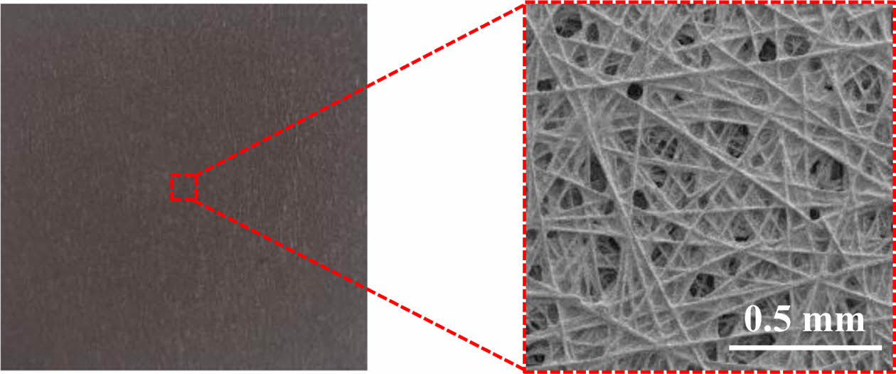
|
Fig. 10 Image of carbon paper-based GDBL |
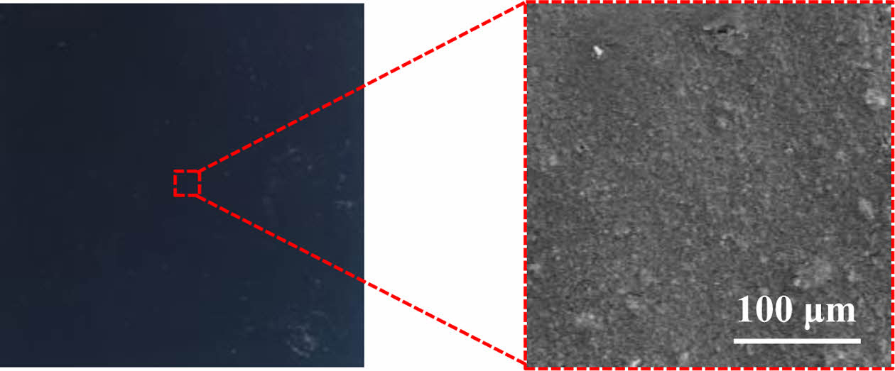
|
Fig. 11 Image of micro porous layer (MPL) |
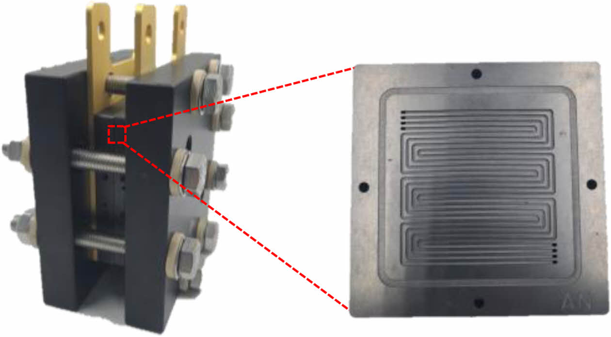
|
Fig. 12 Image of BP in PEMFC unit cell |
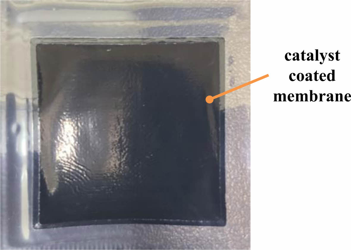
|
Fig. 13 Image of MEA |
|
Table 1 Summary of studies on GDBL categorized by material, key point, and main findings |
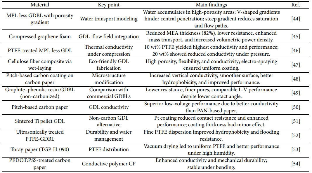
|
Table 2 Summary of studies on MPL categorized by material, key point, and main findings |
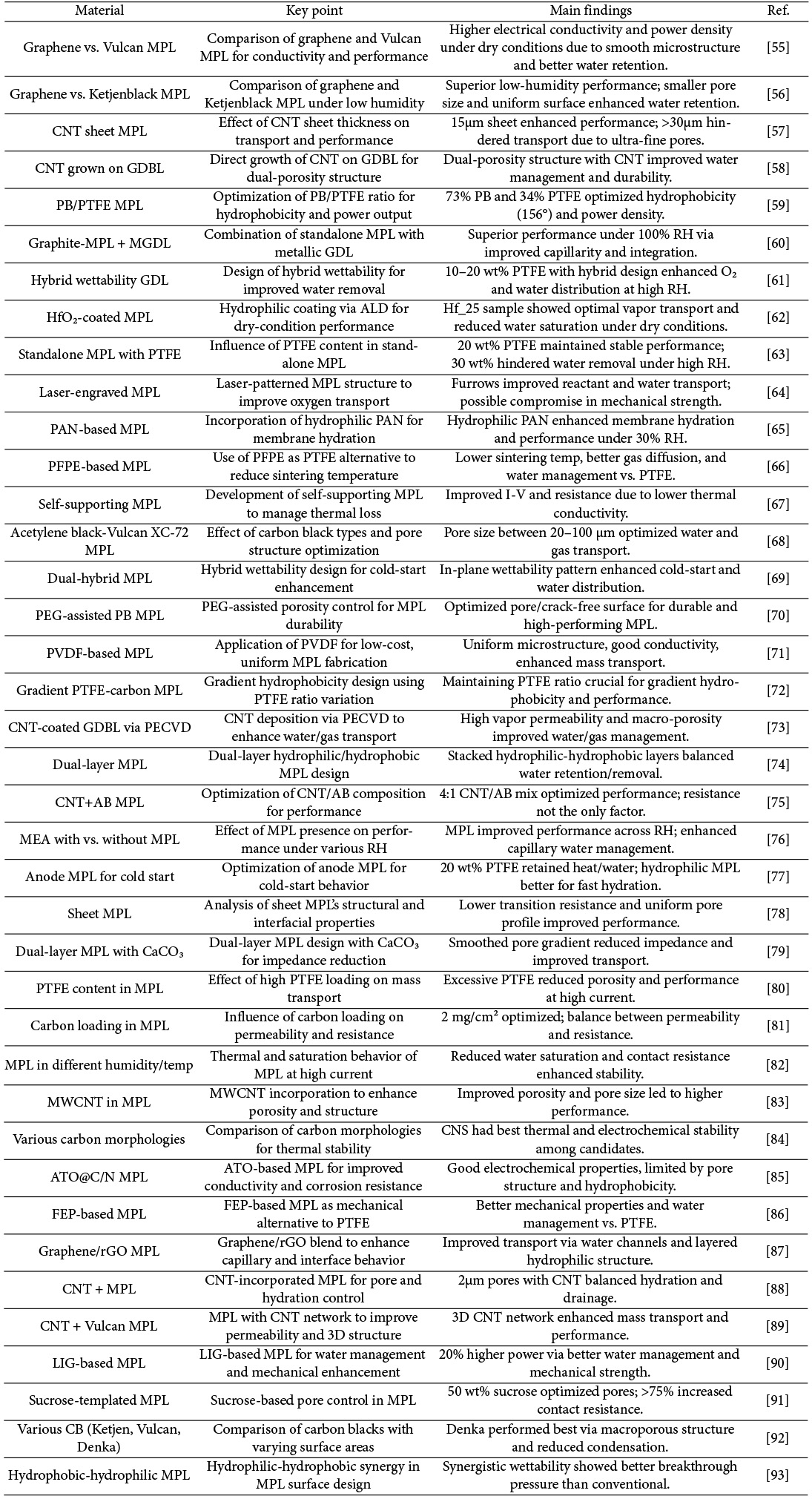
|
Table 3 Summary of studies on BP categorized by material, key point, and main findings |
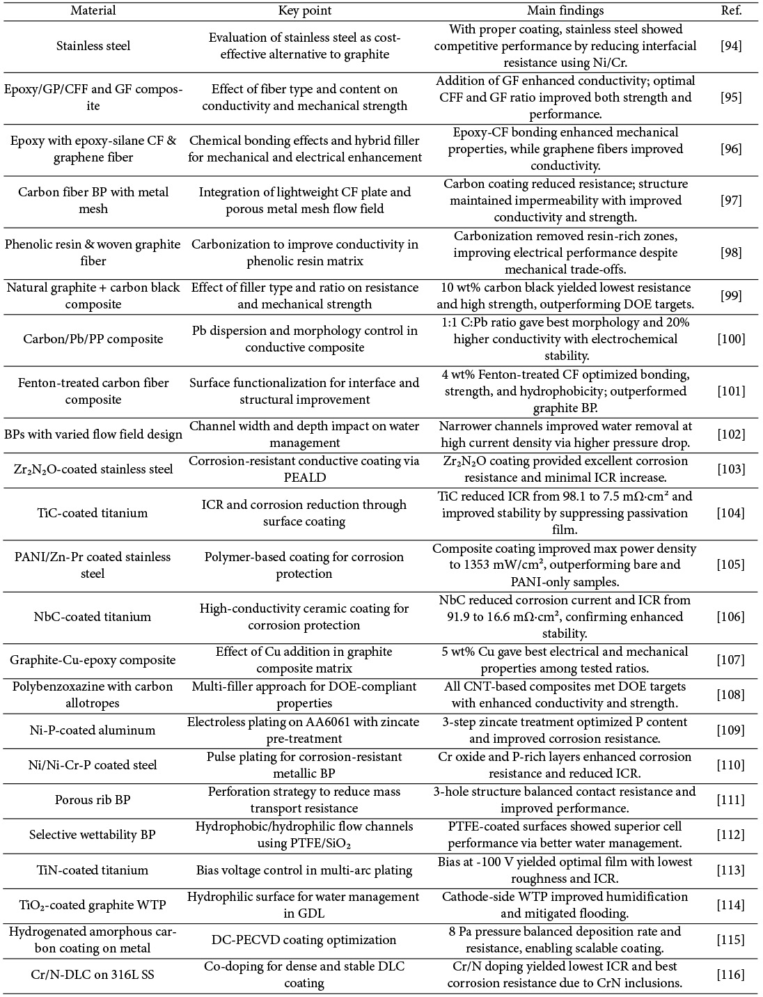
|
Table 4 Summary of studies on MEA categorized by material, key point, and main findings |
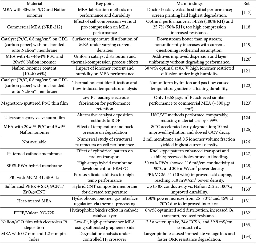
With the projected depletion of fossil fuels by 2070 and growing concerns over environmental degradation, the transition to sustainable energy sources has become imperative. Among the various alternatives, hydrogen energy is gaining significant attention due to its dual potential to address energy scarcity and environmental challenges simultaneously.
In the case of Korea, the domestic production of fossil fuels is extremely limited, making the country heavily dependent on imports. Hydrogen energy, on the other hand, offers a strategic advantage as its production capacity can be enhanced through technological development. Therefore, advancing hydrogen-related technologies, particularly fuel cells, is crucial for securing future energy sovereignty.
This review has examined recent research trends in the key components of Proton exchange Membrane Fuel Cells (PEMFC), namely:
1) Gas Diffusion Backing Layer (GDBL)
2) Micro Porous Layer (MPL)
3) Bipolar Plates (BP)
4) Membrane Electrode Assembly (MEA)
By systematically summarizing advancements in material design, process innovation, and performance evaluation, this review aims to contribute to the dissemination of knowledge and foster collaboration among domestic researchers. It is expected that such efforts will not only enhance the competitiveness of Korea’s fuel cell industry but also accelerate the realization of a hydrogen-based energy society.
This work was supported by the Technological Innovation R&D Program (S3093062) funded by the Ministry of SMEs and Startups (MSS, Korea).
- 1. Hong, S.A., “Development Trends and Future Outlook of Hydrogen and Fuel Cell Technologies”, Ingenium, Vol. 13, 2006, No. 3, pp. 53-61.
- 2. Lee, S.W., “Replace depleting fossil fuels with inexhaustible solar energy”, Journal of Electrical World, No. 286, 2000, pp. 53-61.
- 3. IEA (2020), World Energy Outlook 2020, IEA, Paris, https://www.iea.org/reports/world-energy-outlook-2020
- 4. Park, J.W., Kajiuchi, T., Shindo, Y., Lee, S.M., “Global Warming Caused by Carbon Dioxide and Research Trends in Mitigation Technologies”, Chemical Industry and Technology, Vol. 11, 1993, No. 4, pp. 218-224.
- 5. Kim, J.W., “Prospects for Hydrogen Energy and International Cooperation”, NICE(News & Information for Chemical Engineers), Vol. 22, 2004, No. 2, pp. 112-117.
- 6. MOTIE (2019), Hydrogen Economy Revitalization Roadmap 2019, MOTIE, Sejong, https://www.motie.go.kr/kor/article/ATCLf724eb567/210222/view#
- 7. Kim, H.K. (2021), Overview and Current Status of fuel cell, K-newdeal industry insight report 2021, Export-Import Bank of Korea, Department of Industrial and Economic Research, Seoul, https://www.ctis.re.kr/ko/downloadBbsFile.do?atchmnflNo=6882
- 8. Jang, J.Y., Eom, Y.S., Lim, D.B. (2019), The Present and Future of Fuel Cells, Samjong KPMG Issue monitor 2019, Samjong KPMG, Seoul, https://assets.kpmg.com/content/dam/kpmg/kr/pdf/2019/kr_issuemonitor-112-20190802.pdf
- 9. İnci, M., Türksoy, Ö., “Review of fuel cells to grid interface: Configurations, technical challenges and trends”, Journal of Cleaner Production, Vol. 213, 2019, pp. 1353-1370
-

- 10. A. Kirubakaran, Shailendra Jain, R.K. Nema, “A review on fuel cell technologies and power electronic interface”, Renewable and Sustainable Energy Reviews, Vol. 13, 2009, No. 9, pp. 2430-2440.
-
- 11. K. Song, Y. Wang, Y. Ding, H. Xu, P. Mueller-Welt, T.Stuermlinger, K. Bause, C. Ehrmann, H. W. Weinmann, . Schaefer, J. Fleischer, K. Zhu, F. Weihard, M. Trostmann, M. Schwartze, A. Albers, “Assembly techniques for proton exchange membrane fuel cell stack: A literature review”, Renewable and Sustainable Energy Reviews, Vol. 153, 2022, 111777.
-
- 12. S. Khosravi, Q. Abbas, K. Reichmann, “Electrochemical aspects of interconnect materials in PEMFCs”, International Journal of Hydrogen Energy, Vol. 46, 2021, No. 71, pp. 35420-35447.
-
- 13. Yu, S.J., Hwang, S.J., Kim, S.K., “Trends in Electrode Catalyst Development for Proton Exchange Membrane Fuel Cells”, NICE(News & Information for Chemical Engineers), Vol. 30, 2012, No. 4, pp. 422-425.
- 14. Kim, D.J., Cho, E.A., Hong, S.A., Oh, I.H., “Recent progress in passive direct methanol fuel cells at KIST”, Journal of Power Sources, Vol. 130, 2004, Issues 1-2, pp. 172-177.
-
- 15. Sim, J.P., “Recent Trends in Polymer Electrolyte Membrane Fuel Cell (PEMFC & DMFC) Technology Development” Journal of the Institute of Electronics and Information Engineers, Vol. 14, 2011, No. 1, pp. 17-23.
- 16. X. Cheng, C. Peng, M. You, L. Liu, Y. Zhang, Q. Fan, “Characterization of catalysts and membrane in DMFC lifetime testing”, Electrochimica Acta, Vol. 51, 2006, Issues 22, pp. 4620-4625.
-
- 17. A. S. Aricò, P. Cretı, V. Baglio, E. Modica, V. Antonucci, “Influence of flow field design on the performance of a direct methanol fuel cell”, Journal of Power Sources, Vol. 91, 2000, Issue 2, pp. 202-209.
-
- 18. Yong, Y.W., Azam, A.M.I.N, Masdar, M.S., Zainoodin, A.M., Kamarudin, S.K., “Anode structure with double-catalyst layers for improving the direct ethanol fuel cell performance”, International Journal of Hydrogen Energy, Vol. 45, 2020, Issue 42, pp. 22302-22314.
-
- 19. M. A. Dresch, B. R. Matos, D. R. M. Godoi, M. Linardi, F. C. Fonseca, H. de las Mercedes Villullas, E. I. Santiago, “Advancing direct ethanol fuel cell operation at intermediate temperature by combining Nafion-hybrid electrolyte and well-alloyed PtSn/C electrocatalyst”, International Journal of Hydrogen Energy, Vol. 46, 2021, Issue 24, pp. 13252-13264.
-
- 20. Sinha, V., Mondal, S., “Recent development on performance modelling and fault diagnosis of fuel cell systems”, International Journal of Dynamics and Control, Vol. 6, 2018, pp. 511-528.
-
- 21. O’Hayre, R., Cha, S.W., Colella, W., Prinz, F.B., Fuel cell fundamentals, Wiley, Hoboken, NJ, 2016, pp. 315-317.
- 22. N. Sammes, R. Bove, K. Stahl, “Phosphoric acid fuel cells: Fundamentals and applications”, Current Opinion in Solid State and Materials Science, Vol. 8, 2004, Issue 5, pp. 372-378.
-
- 23. J. Brouwer, F. Jabbari, E. M. Leal, T. Orr, “Analysis of a molten carbonate fuel cell: Numerical modeling and experimental validation”, Journal of Power Sources, Vol. 158, 2006, Issue. 1, pp. 213-224.
-
- 24. Choe, Y.J., Jeon, J.H., Jeon, J.H., “Molten Carbonate Fuel Cell (MCFC) system”, Magazine of the KIPE (The Korean Institute of Power Electronics), Vol. 12, 2007, Issue. 4, pp. 29-33.
- 25. Oh, J.K., Baek, S.H., “Fuel Cell Technology Trends”, KIEE (The Korean Institute of Power Electronics) magazine, Vol. 55, No. 5, 2006, pp. 22-25.
- 26. G. Merle, M. Wessling, K. Nijmeijer, “Anion exchange membranes for alkaline fuel cells: A review”, Journal of Membrane Science, Vol. 377, Issues 1-2, 2011, pp. 1-35.
-
- 27. Y. Wang, D. Y.C. Leung, J. Xuan, H. Wang, “A review on unitized regenerative fuel cell technologies, part B: Unitized regenerative alkaline fuel cell, solid oxide fuel cell, and microfluidic fuel cell”, Renewable and Sustainable Energy Reviews, Vol. 75, 2017, pp. 775-795.
-
- 28. Yoon, K.S., Yoo, J.H., “Technology Development and Research Trends of Solid Oxide Fuel Cells (SOFCs)”, Electrical & Electronic materials, Vol. 33, 2020, pp. 18-27.
- 29. Lee, S.M. (2021), [KISTEP Technology Trend Brief] Fuel Cells 2021-06, KISTEP, Chungcheongbuk-do, https://www.kistep.re.kr/ ease_src/synap/skin/doc.html?imageConverting=true&key= 202105121816251471.pdf&contextPath=/synap/attachFiles/board/0031/202105121816251471.pdf
- 30. Cheongwadae (2020), The Republic of Korea's Carbon Neutrality Declaration 2020, Cheongwadae, Seoul, https://www.mofa. go.kr/www/brd/m_20152/view.do?seq=367872&srchFr=& ;srchTo=&srchWord=&srchTp=&multi_itm_seq=0&itm_seq_1=0&itm_seq_2=0&company_cd=&company_nm=
- 31. Kim, S.H. (2021), Current Status and Challenges of Hydrogen Power Generation (Fuel Cells) in Korea 2021, KDB Future Strategy Research Institute, Seoul, https://eiec.kdi.re.kr/policy/domesticView.do?ac=0000157563
- 32. Bis Research (2016), Global Fuel Cells Market - A Global Study (2016 - 2022) (Focus on Technology Type, Application and Regional Market Dynamics), Bis Research, Fremont, CA, https://bisresearch.com/industry-report/global-fuel-cells-vehicles-market-report-forecast.html
- 33. Hyundai Motor Company (2021), Hyundai Motor company’s Roadmap for Carbon Neutrality. Hyundai Motor Company, Seoul, https://www.hyundai.com/worldwide/ko/brand-journal/sustainable-vision/iaa2021-carbon-neutrality
- 34. Park, J.Y., Kim, J.I., Koo, Y.M. (2020), Strategic Plans to Introduce Fuel Cell Electric Vehicle Cosidering Marketability and Eco-friendly Car Industry 2020, KOTI, Sejong, https://www.koti.re.kr/user/bbs/bassRsrchReprtView.do?bbs_no=670
- 35. Shin, J.Y. (2020), Enterprise analytics reports (Envioneer), KODATA, Seoul, https://kirs.or.kr/research/tech2020_1.html?mode =search&area=code&keyword=317870
- 36. Lee, S.H., Kim, T.H. (2020), “The True Era of Hydrogen: Expanding the Boundaries of the Hydrogen Industry Amid Constraints”, IBK Securities Co. Ltd., Research Division, Seoul, https://m.ibks.com/iko/IKO010301.do?seq=8051
- 37. TechNavio (2016), Global Fuel Cell Market in the Automotive Industry 2015-2019, TechNavio, London, https://www. technavio.com/report/global-automotive-manufacturing-fuel-cell-market-automotive-market
- 38. Innopolis (2020), Global Fuel Cell Market 2020, Innopolis, Daejeon, https://www.innopolis.or.kr/board/view?pageNum= 34&rowCnt=10&no1=636&linkId=44495&menuId=MENU00999&schType=0&schText=&categoryId=05&continent=
- 39. Yoon, S.P., “An Overview of the Current State and Future Prospects of the Fuel Cell Market”, NICE (News & Information for Chemical Engineers), Vol. 29, 2011, Issue. 4
- 40. Park, J.Y., Trends in Global Environmental Policy 2021-02, KEI, Sejong, https://www.kei.re.kr/board.es?mid=a10102060000 &bid=0032&act=view&list_no=57566
- 41. Shin, M.S., Kim, D.E., Park, J.S., “Preparation and Characterizations of poly(arylene ether sulfone)/SiO2 Composite Membranes for Polymer Electrolyte Fuel Cell”, Membrane Journal, Vol. 27, 2017, Issue. 2, pp. 182-188.
-
- 42. Ahn, J.H., Lee, C.H., “Preparation and Characterization of Sulfonated Poly(Arylene Ether Sulfone) Random Copolymer Reinforced Membranes for Fuel Cells,” Membrane Journal, Vol. 26, 2016, Issue. 2, pp. 146-151.
-
- 43. Hwang, J.P., Lee, C.H., “Research Trends and Prospects of Reverse Electrodialysis Membranes”, Membrane Journal, Vol. 27, Issue. 2, 2017, pp. 109-120.
-
- 44. X. Shangguan, Y. Li, Y. Qin, S. Cao, J. Zhang, Y. Yin, “Effect of the porosity distribution on the liquid water transport in the gas diffusion layer of PEMFC”, Electrochimica Acta, Vol. 371, 2021, 137814.
-
- 45. Park, J.E., Lim, J.K., Lim, M.S., Kim, S.J., Kim, O.H., Lee, D.W., Lee, J.H., Cho, Y.H., Sung, Y.E., “Gas diffusion layer/flow-field unified membrane-electrode assembly in fuel cell using graphene foam”, Electrochimica Acta, Vol. 323, 2019, 134808.
-
- 46. T. Chen, S. Liu, J. Zhang, M. Tang, “Study on the characteristics of GDL with different PTFE content and its effect on the performance of PEMFC”, International Journal of Heat and Mass Transfer, Vol. 128, 2019, pp. 1168-1174.
-
- 47. Yarar Kaplan, B., Işıkel Şanlı, L., and Alkan Gürsel, S., “Flexible carbon-cellulose fiber-based composite gas diffusion layer for polymer electrolyte membrane fuel cells”, Journal of Materials Science, Vol. 52, 2017, pp. 4968-4976.
-
- 48. W.-H. Chen, T.-H. Ko, J.-H. Lin, C.-H. Liu, C.-W. Shen, C.-H. Wang, “Influences of Gas Diffusion Layers with Pitch-based Carbon Coated in Polymer Electrolyte Membrane Fuel Cell”, International Journal of Electrochemical Science, Vol. 6, 2011, Issue. 6, pp. 2192-2200.
-
- 49. R. Taherian, M. M. Ghorbani, M. Nasr, S. R. Kiahosseini, “Fabrication and investigation of polymer-based carbon composite as gas diffusion layer of proton exchange membrane of fuel cells”, Materials Science: Advanced Composite Materials, Vol. 2, 2018, Issue. 1, pp. 1-12.
-
- 50. J.-H. Lin, W.-H. Chen, S.-H. Su, Y.-K. Liao, T.-H. Ko, “Carbon film coating on gas diffusion layer for proton exchange membrane fuel cells”, Journal of Power Sources, Vol. 184, 2008, Issue. 1, pp. 38-43.
-
- 51. T. Hottinen, M. Mikkola, T. Mennola, P. Lund, “Titanium sinter as gas diffusion backing in PEMFC”, Journal of Power Sources, Vol. 118, 2003, Issues. 1-2, pp. 183-188.
-
- 52. S. Yu, J. Hao, J. Li, L. Zhang, “Effect of distribution of polytetrafluoroethylene on durability of gas diffusion backing in proton exchange membrane fuel cell”, Materials Research Bulletin, Vol. 122, 2020, 110684.
-
- 53. H. Ito, T. Iwamura, S. Someya, T. Munakata, A. Nakano, Yun Heo, M.Ishida, H. Nakajima, T. Kitahara, “Effect of through-plane polytetrafluoroethylene distribution in gas diffusion layers on performance of proton exchange membrane fuel cells”, Journal of Power Sources, Vol. 306, 2016, pp. 289-299.
-
- 54. Kim, H.U., Lee, Y.J., Park, G.G., Park, S.H., Choi, Y.Y., Yoo, Y.J., “Fabrication of carbon paper containing PEDOT:PSS for use as a gas diffusion layer in proton exchange membrane fuel cells”, Carbon, Vol. 85, 2015, pp. 422-428.
-
- 55. A. Ozden, S. Shahgaldi, X. Li, F. Hamdullahpur, “A graphene-based microporous layer for proton exchange membrane fuel cells: Characterization and performance comparison”, Renewable Energy, Vol. 126, 2018, pp. 485-494.
-
- 56. A. Ozden, S. Shahgaldi, J. Zhao, X. Li, F. Hamdullahpur, “Assessment of graphene as an alternative microporous layer material for proton exchange membrane fuel cells”, Fuel, Vol. 215, 2018, pp. 726-734.
-
- 57. Kim, J.Y., Kim, H.O., Song, H.J., Kim, D.S., Kim, G.H., Im, D.S., Jeong, Y.J., Park, T.H., “Carbon nanotube sheet as a microporous layer for proton exchange membrane fuel cells”, Energy, Vol. 227, 2021, 120459.
-
- 58. M. Fontana, R. Ramos, A. Morin, J. Dijon, “Direct growth of carbon nanotubes forests on carbon fibers to replace microporous layers in proton exchange membrane fuel cells”, Carbon, Vol. 172, 2021, pp. 762-771.
-
- 59. B. Laoun, H. A. Kasat, R. Ahmad, A. M. Kannan, “Gas diffusion layer development using design of experiments for the optimization of a proton exchange membrane fuel cell performance”, Energy, Vol. 151, 2018, pp. 689-695.
-
- 60. F. Hendricks, J. Chamier, S. Tanaka, “Membrane electrode assembly performance of a standalone microporous layer on a metallic gas diffusion layer”, Journal of Power Sources, Vol. 464, 2020, 228222.
-
- 61. Y. Wang, T. Liu, W. He, S. Wang, S. Liu, L. Yue, H. Li, “Performance enhancement of polymer electrolyte membrane fuel cells with a hybrid wettability gas diffusion layer”, Energy Conversion and Management, Vol. 223, 2020, 113297.
-
- 62. Lim, I.S., Kang, B.H., Park, J.Y., Kim, M.S., “Performance improvement of polymer electrolyte membrane fuel cell by gas diffusion layer with atomic-layer-deposited HfO2 on microporous layer”, Energy Conversion and Management, Vol. 236, 2021, 114070.
-
- 63. A.K.C. Wong, N. Ge, P. Shrestha, H. Liu, K. Fahy, A. Bazylak, “Polytetrafluoroethylene content in standalone microporous layers: Tradeoff between membrane hydration and mass transport losses in polymer electrolyte membrane fuel cells”, Applied Energy, Vol. 240, 2019, pp. 549-560.
-
- 64. Choi, J.W., Lee, S.H., Shim, B.S., Yi, J.S., Kim, D.H., Park, S.K., “Unveiling water drainage through microporous layer with laser-ablated open furrows in proton exchange membrane fuel cells”, Journal of Power Sources, Vol. 491, 2021, 229563.
-
- 65. T. Kitahara, H. Nakajima, M. Inamoto, M. Morishita, “Novel hydrophilic and hydrophobic double microporous layer coated gas diffusion layer to enhance performance of polymer electrolyte fuel cells under both low and high humidity”, Journal of Power Sources, Vol. 234, 2013, pp. 129-138.
-
- 66. Balzarotti R., Latorrata S., Stampino P.G., Cristiani C., Dotelli G., “Development and Characterization of Non-Conventional Micro-Porous Layers for PEM Fuel Cells”, Energies, Vol. 8, 2015, pp. 7070-7083.
-
- 67. H. Ito, Y. Heo, M. Ishida, A. Nakano, S. Someya, T. Munakata, “Application of a self-supporting microporous layer to gas diffusion layers of proton exchange membrane fuel cells”, Journal of Power Sources, Vol. 342, 2017, pp. 393-404.
-
- 68. G. Lin, S. Liu, S. Qu, T. Li, Z. Liang, Y. Hu, F. Liu, “Effects of thickness and hydrophobicity of double microporous layer on the performance in proton exchange membrane fuel cells”, Journal of Applied Polymer Science, Vol. 138, 2021, Issue. 18, 50355.
-
- 69. Wang, G., Utaka, Y., Wang, S., “Effect of Dual Porous Layers with Patterned Wettability on Low-Temperature Start Performance of Polymer Electrolyte Membrane Fuel Cell”, Energies, Vol. 13, 2020, Issue. 14, 3529.
-
- 70. G. Athanasaki, Q. Wang, X. Shi, N. Chauhan, V. Vimala, L. Cindrella, R. Ahmad, A.M. Kannan, “Design and development of gas diffusion layers with pore forming agent for proton exchange membrane fuel cells at various relative humidity conditions”, International Journal of Hydrogen Energy, Vol. 46, 2021, Issue. 9, pp. 6835-6844.
-
- 71. Park, S.B., Kim, S.J., Park, Y.I., Oh, M.H., “Fabrication of GDL microporous layer using PVDF for PEMFCs”, Journal of Physics: Conference Series, Vol. 165, 2009, 012046.
-
- 72. K. Zhou, T. Li, Y. Han, J. Wang, J. Chen, K. Wang, “Optimizing the hydrophobicity of GDL to improve the fuel cell performance”, RSC Advances, Vol. 11, 2021, pp. 2010-2019.
-
- 73. Z. Xie, G. Chen, X. Yu, M. Hou, Z. Shao, S. Hong, C. Mu, “Carbon nanotubes grown in situ on carbon paper as a microporous layer for proton exchange membrane fuel cells”, International Journal of Hydrogen Energy, Vol. 40, 2015, Issue. 29, pp. 8958-8965.
-
- 74. Chun, J.H., Park, K.T., Jo, D.H., Lee, J.Y., Kim, S.G., Park, S.H., Lee, E.S., Jyoung, J.Y., Kim, S.H., “Development of a novel hydrophobic/hydrophilic double micro porous layer for use in a cathode gas diffusion layer in PEMFC”. International Journal of Hydrogen Energy, Vol. 36, 2011, Issue. 14, pp. 8422-8428.
-
- 75. S.-Y. Lin, M.-H. Chang, “Effect of microporous layer composed of carbon nanotube and acetylene black on polymer electrolyte membrane fuel cell performance”, International Journal of Hydrogen Energy, Vol. 40, 2015, Issue. 24, pp. 7879-7885.
-
- 76. J. Shan, R. Lin, X. Chen, X. Diao, “EIS and local resolved current density distribution analysis on effects of MPL on PEMFC performance at varied humidification”, International Journal of Heat and Mass Transfer, Vol. 127, 2018, Part. C, pp. 1076-1083.
-
- 77. R. Lin, D. Zhong, S. Lan, R. Guo, Y. Ma, X. Cai, “Experimental validation for enhancement of PEMFC cold start performance: Based on the optimization of micro porous layer”, Applied Energy, Vol. 300, 2021, 117306.
-
- 78. J. Lee, H. Liu, M.G. George, R. Banerjee, N. Ge, S. Chevalier, T. Kotaka, Y. Tabuchi, A. Bazylak, “Microporous layer to carbon fibre substrate interface impact on polymer electrolyte membrane fuel cell performance”, Journal of Power Sources, Vol. 422, 2019, pp. 113-121.
-
- 79. T. Li, K. Wang, J. Wang, Y. Liu, Y. Han, Z. Xu, G. Lin, Yong Liu, “Optimization of GDL to improve water transferability”, Renewable Energy, Vol. 179, 2021, pp. 2086-2093.
-
- 80. G. Velayutham, “Effect of micro-layer PTFE on the performance of PEM fuel cell electrodes”, International Journal of Hydrogen Energy, Vol. 36, 2011, Issue. 22, pp. 14845-14850.
-
- 81. Sim, J.B., Kang, M.S., Min, K.D., “Effects of basic gas diffusion layer components on PEMFC performance with capillary pressure gradient”, International Journal of Hydrogen Energy, Vol. 46, 2021, Issue. 54, pp. 27731-27748.
-
- 82. J. T. Gostick, M. A. Ioannidis, M. W. Fowler, M. D. Pritzker, “On the role of the microporous layer in PEMFC operation”, Electrochemistry Communications, Vol. 11, 2009, Issue. 3, pp. 576-579.
-
- 83. J. Lee, R. Banerjee, M. G. George, D. Muirhead, P. Shrestha, H. Liu, N. Ge, S. Chevalier, A. Bazylak, “Multiwall Carbon Nanotube-Based Microporous Layers for Polymer Electrolyte Membrane Fuel Cells”, Journal of The Electrochemical Society, Vol. 164, 2017, No. 12, pp. 1149-1157.
-
- 84. H. Zamora, P. Cañizares, M. A. Rodrigo, J. Lobato, “Improving of Micro Porous Layer based on Advanced Carbon Materials for High Temperature Proton Exchange Membrane Fuel Cell Electrodes”, Fuel Cells, Vol. 15, 2015, Issue. 2, pp. 375-383.
-
- 85. Y. Jiang, J. Hao, M. Hou, H. Zhang, X. Li, Z. Shao, Baolian Yi, “A new microporous layer material to improve the performance and durability of polymer electrolyte membrane fuel cells”, RSC Advances, Vol.5, 2015, pp. 104095-104100.
-
- 86. Park, S.B., Park, Y.I., “Fabrication of gas diffusion layer (GDL) containing microporous layer using flourinated ethylene prophylene (FEP) for proton exchange membrane fuel cell (PEMFC)”, International Journal of Precision Engineering and Manufacturing, Vol. 13, 2012, pp. 1145-1151.
-
- 87. M. J. Leeuwner, A. Patra, D. P. Wilkinson, E. L. Gyenge, “Graphene and reduced graphene oxide based microporous layers for high-performance proton-exchange membrane fuel cells under varied humidity operation”, Journal of Power Sources, Vol. 423, 2019, pp. 192-202.
-
- 88. T. Kitahara, H. Nakajima, K. Okamura, “Gas diffusion layers coated with a microporous layer containing hydrophilic carbon nanotubes for performance enhancement of polymer electrolyte fuel cells under both low and high humidity conditions”, Journal of Power Sources, Vol. 283, 2015, pp. 115-124.
-
- 89. G.-B. Jung, W.-J. Tzeng, T.-C. Jao, Y.-H. Liu, C.-C. Yeh, “Investigation of porous carbon and carbon nanotube layer for proton exchange membrane fuel cells”, Applied Energy, Vol. 101, 2013, pp. 457-464.
-
- 90. A. Tiliakos, A.M.I. Trefilov, E.Tanasă, A. Balan, I. Stamatin, “Laser-induced graphene as the microporous layer in proton exchange membrane fuel cells”, Applied Surface Science, Vol. 504, 2020, 144096.
-
- 91. G. Selvarani, A. K. Sahu, P. Sridhar, S. Pitchumani, A. K. Shukla, “Effect of diffusion-layer porosity on the performance of polymer electrolyte fuel cells”, Journal of Applied Electrochemistry, Vol. 38, 2008, pp. 357-362.
-
- 92. J. Yu, Y. Yoshikawa, T. Matsuura, M. N. Islam, M. Hori, “Preparing Gas-Diffusion Layers of PEMFCs with a Dry Deposition Technique”, Electrochemical and Solid-State Letters, Vol. 8, 2005, Issue. 3, pp. A152-A155.
-
- 93. F. Guo, X. Yang, H. Jiang, Y. Zhu, C. Li, “An ultrasonic atomization spray strategy for constructing hydrophobic and hydrophilic synergistic surfaces as gas diffusion layers for proton exchange membrane fuel cells”, Journal of Power Sources, Vol. 451, 2020, 227784.
-
- 94. D.P. Davies, P.L. Adcock, M. Turpin, S.J. Rowen, “Stainless steel as a bipolar plate material for solid polymer fuel cells”, Journal of Power Sources, Vol. 86, 2000, Issues 1-2, pp. 237-242.
-
- 95. Lee, J.Y., Lee, W.K., Rim, H.R., Joung. G.B., Lee, H.K., “Effect of Carbon Fiber Filament and Graphite Fiber on the Mechanical Properties and Electrical Conductivity of Elastic Carbon Composite Bipolar Plate for PEMFC”, Journal of Hydrogen and New energy, Vol. 25, 2014, No. 2, pp. 131-138.
-
- 96. Lee, H.K., Han, K.S., “Effect of Surface-Modified Carbon Fiber on the Mechanical Properties of Carbon/Epoxy Composite for Bipolar Plate of PEMFC”, Journal of Hydrogen and New energy, Vol. 31, 2020, No. 1, pp. 49-56.
-
- 97. Choi, H.U., Seo, D.J., Choi, W.Y., Choi, S.W., Lee, M.H., Park, Y.J., Kim, T.Y., Yoon, Y.G., Yi, S.C., Jung, C.Y., “An ultralight-weight polymer electrolyte fuel cell based on woven carbon fiber-resin reinforced bipolar plate”, Journal of Power Sources, Vol. 484, 2021, 229291.
-
- 98. Y.-D. Kuan, C.-W. Ciou, M.-Y. Shen, C.-K. Wang, R. Z. Fitriani, C.-Y. Lee, “Bipolar plate design and fabrication using graphite reinforced composite laminate for proton exchange membrane fuel cells”, International Journal of Hydrogen Energy, Vol. 46, 2021, Issue. 31, pp. 16801-16814.
-
- 99. Lim, J.W., “Development of Carbon Composite Bipolar Plates for PEMFC”, Composites Research, Vol. 32, 2019, No. 5, pp. 222-228.
-
- 100. Thangarasu, S., Jung, H.Y., Wee, J.H., Kim, Y.A., Roh, S.H., “A new strategy of carbon - Pb composite as a bipolar plate material for unitized regenerative fuel cell system”, Electrochimica Acta, Vol. 391, 2021, 138921.
-
- 101. B. Lv, Z. Shao, L. He, Y. Gou, S. Sun, “A novel graphite/phenolic resin bipolar plate modified by doping carbon fibers for the application of proton exchange membrane fuel cells”, Progress in Natural Science: Materials International, Vol. 30, 2020, Issue. 6, pp. 876-881.
-
- 102. C. Wang, Q. Zhang, S. Shen, X. Yan, F. Zhu, X. Cheng, J. Zhang, “The respective effect of under-rib convection and pressure drop of flow fields on the performance of PEM fuel cells”, Scientific Reports, Vol. 7, 2017, 43447.
-
- 103. X.-Z. Wang, T. P. Muneshwar, H.-Q. Fan, K. Cadien, J.-L. Luo, “Achieving ultrahigh corrosion resistance and conductive zirconium oxynitride coating on metal bipolar plates by plasma enhanced atomic layer deposition”, Journal of Power Sources, Vol. 397, 2018, pp. 32-36.
-
- 104. J. Shi, P. Zhang, Y. Han, H. Wang, X. Wang, Y. Yu, J. Sun, “Investigation on electrochemical behavior and surface conductivity of titanium carbide modified Ti bipolar plate of PEMFC”, International Journal of Hydrogen Energy, Vol. 45, 2020, Issue. 16, pp. 10050-10058.
-
- 105. M.A. Deyab, G. Mele, “Stainless steel bipolar plate coated with polyaniline/Zn-Porphyrin composites coatings for proton exchange membrane fuel cell”, Scientific Reports, Vol. 10, 2020, 3277.
-
- 106. P. Zhang, C. Hao, Y. Han, F. Du, H. Wang, X. Wang, J. Sun, “Electrochemical behavior and surface conductivity of NbC modified Ti bipolar plate for proton exchange membrane fuel cell”, Surface and Coatings Technology, Vol. 397, 2020, 126064.
-
- 107. M. Soleimani Alavijeh, H. Kefayati, A. N. Golikand, S. Shariati, “Synthesis and characterization of epoxy/graphite/nano-copper nanocomposite for the fabrication of bipolar plate for PEMFCs”, Journal of Nanostructure in Chemistry, Vol. 9, 2019, pp. 11-18.
-
- 108. S. Witpathomwong, M. Okhawilai, C. Jubsilp, P. Karagiannidis, S. Rimdusit, “Highly filled graphite/graphene/carbon nanotube in polybenzoxazine composites for bipolar plate in PEMFC”, International Journal of Hydrogen Energy, Vol. 45, 2020, Issue. 55, pp. 30898-30910.
-
- 109. A.G. González-Gutiérrez, M.A. Pech-Canul, G. Chan-Rosado, P.J. Sebastian, “Studies on the physical and electrochemical properties of Ni-P coating on commercial aluminum as bipolar plate in PEMFC”, Fuel, Vol. 235, 2019, pp. 1361-1367.
-
- 110. U. K. Chanda, A. Behera, S. Roy, S. Pati, “Evaluation of Ni-Cr-P coatings electrodeposited on low carbon steel bipolar plates for polymer electrolyte membrane fuel cell”, International Journal of Hydrogen Energy, Vol. 43, 2018, Issue. 52, pp. 23430-23440.
-
- 111. Baik, K.D., Seo, I.S., “Metallic bipolar plate with a multi-hole structure in the rib regions for polymer electrolyte membrane fuel cells”, Applied Energy, Vol. 212, 2018, pp. 333-339.
-
- 112. E. E. Kahveci, I. Taymaz, “Experimental study on performance evaluation of PEM fuel cell by coating bipolar plate with materials having different contact angle”, Fuel, Vol. 253, 2019, pp. 1274-1281.
-
- 113. T. Li, Z. Yan, Z. Liu, Y. Yan, Y. Chen, “Surface microstructure and performance of TiN monolayer film on titanium bipolar plate for PEMFC”, International Journal of Hydrogen Energy, Vol. 46, 2021, Issue. 61, pp. 31382-31390.
-
- 114. Z. Wang, Y. Zeng, S. Sun, Z. Shao, B. Yi, “Improvement of PEMFC water management by employing water transport plate as bipolar plate”, International Journal of Hydrogen Energy, Vol. 42, 2017, Issue. 34, pp. 21922-21929.
-
- 115. J. Che, P. Yi, L. Peng, X. Lai, “Impact of pressure on carbon films by PECVD toward high deposition rates and high stability as metallic bipolar plate for PEMFCs”, International Journal of Hydrogen Energy, Vol. 45, 2020, Issue. 32, pp. 16277-16286.
-
- 116. H. Dong, S. He, X. Wang, C. Zhang, D. Sun, “Study on conductivity and corrosion resistance of N-doped and Cr/N co-doped DLC films on bipolar plates for PEMFC”, Diamond and Related Materials, Vol. 110, 2020, 108156.
-
- 117. Jeong, J.H., Song, M.H., Chung H.B., Na, I.C., Lee, J.H., Lee, H., Park, K.P., “Performance and Durability of PEMFC MEAs Fabricated by Various Methods”, Korean Chemical Engineering Research, Vol. 52, 2014, Issue. 5, pp. 558-563.
-
- 118. N. K. Shrivastava, A. Chatterjee, T. A.L. Harris, “Effect of cell compression on the performance of a non-hot-pressed MEA for PEMFC”, International Journal of Energy Research, Vol. 44, 2019, pp. 370-387.
-
- 119. M. Wang, H. Guo, C. Ma, “Temperature distribution on the MEA surface of a PEMFC with serpentine channel flow bed”, Journal of Power Sources, Vol. 157, 2006, Issue. 1, pp. 181-187.
-
- 120. Jang, H.S., Cho, E.A., “Effects of Additives and Hot-Pressing Conditions on the Surface and Performance of MEAs for PEMFCs”, Journal of the Korean Hydrogen and New Energy Society, Vol. 21, No. 5, 2010, pp. 398-404.
-
- 121. Jeon, S.Y., Lee, J.S., Gema M. Rios, Kim, H.J., Lee, S.Y., Cho, E.A., Lim, T.H., Jang, J.H., “Effect of ionomer content and relative humidity on polymer electrolyte membrane fuel cell (PEMFC) performance of membrane-electrode assemblies (MEAs) prepared by decal transfer method”, International Journal of Hydrogen Energy, Vol. 35, 2010, Issue. 18, pp. 9678-9686.
-
- 122. H. Guo, M. H. Wang, F. Ye, C. F. Ma, “Experimental study of temperature distribution on anodic surface of MEA inside a PEMFC with parallel channels flow bed”, International Journal of Hydrogen Energy, Vol. 37, 2012, Issue. 17, pp. 13155-13160.
-
- 123. A. Ostroverkh, M. Dubau, V. Johánek, M. Václavů, B. Šmíd, K. Veltruská, Y. Ostroverkh, R. Fiala, V. Matolín, “Efficient Pt-C MEA for PEMFC with Low Platinum Content Prepared by Magnetron Sputtering”, Fuel Cells, Vol. 18, 2018, No. 1, pp. 51-56.
-
- 124. V. Yarlagadda, S. E. McKinney, C. L. Keary, L. Thompson, B. Zulevi and A. Kongkanand, “Preparation of PEMFC Electrodes from Milligram-Amounts of Catalyst Powder”, Journal of The Electrochemical Society, Vol. 164, 2017, Issue. 7, pp. F845-F849.
-
- 125. D. Rohendi, E.H. Majlan, A.B. Mohamad, W.R.W. Daud, A.A.H. Kadhum, L.K. Shyuan, “Effects of temperature and backpressure on the performance degradation of MEA in PEMFC”, International Journal of Hydrogen Energy, Vol. 40, 2015, Issue. 34, pp. 10960-10968.
-
- 126. S. Mohanty, A. N. Desai, S. Singh, Venkatasailanathan Ramadesigan, Shaneeth M, “Effects of the membrane thickness and ionomer volume fraction on the performance of PEMFC with U-shaped serpentine channel”, International Journal of Hydrogen Energy, Vol. 46, 2021, Issue. 39, pp. 20650-20663.
-
- 127. S. Cuynet, A. Caillard, J. Bigarré, P. Buvat, “Impact of the patterned membrane morphology on PEMFC performances of ultra-low platinum loaded MEAs”, International Journal of Hydrogen Energy, Vol. 42, 2017, Issue. 12, pp. 7974-7985.
-
- 128. A. R. Kim, C. J. Park, M. Vinothkannan, D. J. Yoo, “Sulfonated poly ether sulfone/heteropoly acid composite membranes as electrolytes for the improved power generation of proton exchange membrane fuel cells”, Composites Part B: Engineering, Vol. 155, 2018, pp. 272-281.
-
- 129. Y.-J. Kuo, H.-L. Lin, “Effects of mesoporous fillers on properties of polybenzimidazole composite membranes for high-temperature polymer fuel cells”, International Journal of Hydrogen Energy, Vol. 43, 2018, Issue. 9, pp. 4448-4457.
-
- 130. T. Roy, S. K. Wanchoo, K. Pal, “Synergetic proton-conducting effect of sulfonated PEEK-MO2-CNT membranes for PEMFC applications”, Ionics, Vol. 27, 2021, pp. 4859-4873.
-
- 131. R. P. Dowd Jr., Y. Li, T. V. Nguyen, “Controlling the ionic polymer/gas interface property of a PEM fuel cell catalyst layer during membrane electrode assembly fabrication”, Journal of Applied Electrochemistry, Vol. 50, 2020, pp. 993-1006.
-
- 132. Kim, D.H., Jung, H.S., Chun, H.S., Pak, C.H., “Enhanced membrane electrode assembly performance by adding PTFE/Carbon black for high temperature polymer electrolyte membrane fuel cell”, International Journal of Hydrogen Energy, Vol. 46, 2021, Issue. 57, pp. 29424-29431.
-
- 133. F. Mahdi, L. Naji, A. Rahmanian, “Fabrication of membrane electrode assembly based on nafion/sulfonated graphene oxide nanocomposite by electroless deposition for proton exchange membrane fuel cells”, Surfaces and Interfaces, Vol. 23, 2021, 100925.
-
- 134. B.T. Huang, Y. Chatillon, C. Bonnet, F. Lapicque, S. Leclerc, M. Hinaje, S. Raël, “Experimental investigation of pinhole effect on MEA/cell aging in PEMFC”, International Journal of Hydrogen Energy, Vol. 38, 2013, Issue. 1, pp. 543-550.
-
 This Article
-
2025; 38(3): 272-299
Published on Jun 30, 2025
- 10.7234/composres.2025.38.3.272
- Received on Jun 8, 2025
- Revised on Jun 28, 2025
- Accepted on Jun 30, 2025
Services
- Abstract
1. introduction
2. fuel cell
3. pemfc research trend
4. conclusion
- Acknowledgements
- References
- Full Text PDF
Shared
Correspondence to
- Sang Eui Lee
-
Department of Mechanical Engineering, Inha University, Incheon 22212, Republic of Korea
- E-mail: selee@inha.ac.kr
Gangnam Mirae Tower, Suite 601, 174 Saimdang-ro, Seocho-gu, Seoul 06627, South Korea
Tel: +82-2-598-1550 Fax: +82-2-598-1557 E-mail: composites@kscm.re.kr