


- Evaluation of the Influence of Pyrolysis Temperature on the Electrical Heating Properties of Si-O-C Fiber
Sanghun Kim*, **, Seong-Gun Bae*, **, Bum-Mo Koo*, **, Dong-Geun Shin*† , Yeong-Geun Jeong**
* Aerospace Convergence Materials Center, Korea Institute of Ceramic Engineering & Technology, Jinju 52851, Korea
** Department of Convergence, Pusan National University, Busan 46241, KoreaThis article is an open access article distributed under the terms of the Creative Commons Attribution Non-Commercial License (http://creativecommons.org/licenses/by-nc/4.0) which permits unrestricted non-commercial use, distribution, and reproduction in any medium, provided the original work is properly cited.
Silicon carbide (SiC) fibers exhibit excellent heat and chemical resistance at high temperatures. In this study, polycarbosilane melt spinning, oxidation curing, and pyrolysis were performed to fabricate amorphous SiC fibers, and their resistance heating characteristics were evaluated. A stick-type amorphous silicon carbide fiber heating element was manufactured, and the resistance was measured using the two-point probe method. The structural, electrical, and heating characteristics were evaluated at different pyrolysis temperatures. The fiber produced at 1300°C displayed the highest conductivity and the maximum heating compared to the fibers produced at 1200°C and 1400°C. This may be attributed to difference in the structures of the fibers, particularly the SiC and graphitic carbon structures.
Keywords: Silicon carbide fiber, Stick type, Heating element, Sintering
Ceramic materials generate heat by resisting the electric current; therefore, they are widely used as heating elements. Such ceramic heating elements distribute heat evenly and are less likely to cause fires when in contact with flammable materials. Additionally, they provide long-lasting durability against direct heating and are therefore widely used in heat-treatment furnaces [1].
Ceramic heating elements are mainly manufactured using ceramic powders such as SiC and MoSi2, which require a long heat treatment process at high temperatures and a process to make the particle size uniform before and after the heat treatment [1]. In addition, there is a high risk of thermal shock damage to brittle ceramics due to the stress buildup by rapid heating or cooling.
Recently, research has been conducted on ceramic fiber-type heating elements, which decrease the drawbacks typical of ceramic powder-type heating elements [2-4]. Ceramic fibers maintain a constant pressure, temperature, and winding speed through the melt spinning process. Therefore, fibers with a uniform diameter can be manufactured without additional processing. In addition, when comparing productivity, ceramic fibers are superior to monolithic ceramics because they pyrolyze within a short time at a relatively low temperature.
Carbon and SiC are mainly used as materials for ceramic fibers. Carbon fiber has excellent electrical and mechanical properties but has low oxidation resistance which makes it difficult to use in the air above 700°C; therefore, it is mainly used only in the low-temperature range [5,6]. However, silicon carbide (SiC) fiber, because of its superior oxidation resistance and high heat resistance at high temperatures compared to carbon fiber, can be used in the air above 1000°C. It is not only used in heating elements but also in high-temperature environments, such as national defense and nuclear energy [7-9].
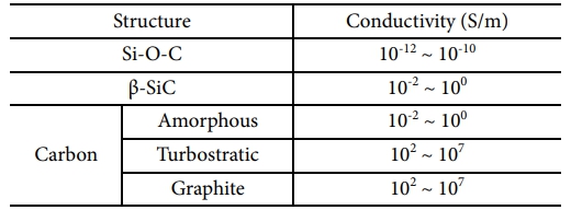
SiC fibers are prepared by melt spinning of polycarbosilane (PCS) as a precursor material. In the 1970s, Yajima reported the synthesis of PCS under a high-temperature and high-pressure reaction of polydimethylsilane (PDMS) [10-13]. Melt spinning, oxidation curing, and pyrolysis processes were sequentially performed to make silicon oxycarbide (Si-O-C) fibers [14,15]. Silicon oxycarbide fibers are composed of amorphous Si-O-C matrix, nanocrystalline silicon carbide (β-SiC), and a residual turbostratic carbon phase. It has various structural and mechanical characteristics depending on the conditions of the manufacturing process [16-19]. In particular, studies have been conducted that are related to the evaluation of electrical properties based on microstructural changes that occur during pyrolysis. Electrical conductivities of SiC fiber derived from polycarbosilane has 0.3~120 (Wm)-1 at room temperature and increased with heating temperature depends on their microstructural composition such as degree of crystallization, amount of amorphous matrix, and residual carbon. They depend on the fiber curing and heat-treatment conditions and are major factors related to the electrical properties of the fiber [20-23]. The electrical conductivity of each structure constituting the fibers is listed in Table 1.
In this study, amorphous SiC fibers were prepared by melt spinning and thermal oxidation of PCS precursors and their structural and electrical properties were evaluated for different values of the pyrolysis temperature. A heating element in the form of a stick was manufactured to evaluate the electrical resistance heating properties
2.1 Manufacturing of Si-O-C fibers and heating elements
To manufacture the Si-O-C fibers, polycarbosilane (PCS) was first placed into a spinneret of the melt spinning device, and then the melt spinning was performed at 240°C while maintaining a nitrogen atmosphere. The melt spinning process was carried out by fixing the spinning pressure (10 kPa), temperature (240°C), and winding speed (250 rpm), thus keeping the diameter of the fiber constant and controlling its resistance. The prepared PCS fiber was subjected to an oxidation-curing process at 200°C for 8 hours in a drying oven using a convection flow method. Thereafter, Si-O-C fibers were prepared by pyrolysis for 1 hour at temperatures of 1200°C, 1300°C, and 1400°C in an Ar atmosphere.
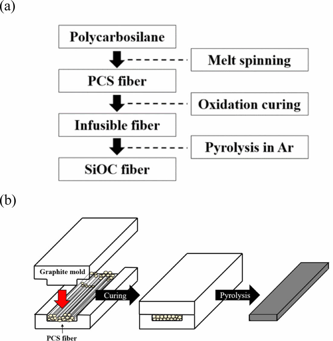
Fig. 1 shows the manufacturing process of Si-O-C fibers and the heating elements. To manufacture a stick-shaped heating element, a bundle of PCS fibers was placed inside a graphite mold (120 × 40 × 20 mm3), and the weak pressure was applied during the thermal oxidation curing process for the contact among fiber surfaces and densification of the heating element. Subsequently, pyrolysis was performed while maintaining a pressurized state.
2.2 Analysis of the structure of Si-O-C fibers
X-ray diffraction (XRD; D8Advance, Bruker, Germany) analysis was performed to analyze the crystal structure of the amorphous Si-O-C fibers corresponding to different pyrolysis temperature values, and the diffraction measurement range was set to 2θ = 20°–80°. Thermogravimetric analysis (TGA; STA-449-F3, NETZSCH, Germany) was performed to observe the weight change due to the decomposition behavior of the amorphous Si-O-C structure that occurred with an increase in pyrolysis temperature, and it was analyzed up to 1600°C at a rate of 10°C/min in an Ar atmosphere. The cross-sectional microstructure of the amorphous Si-O-C fiber was analyzed by field-emission scanning electron microscopy (FE-SEM; JEOL1614, JEOL, Japan). Raman spectroscopy (LabRam Aramis, Horiba, Japan) and X-ray photoelectron spectroscopy (XPS; NEXSA, Thermo Fisher Scientific, USA) were used to analyze the carbon structure of the fiber surface. Raman spectroscopy was performed in the wavenumber range of 400– 2000 cm-1 using 532 nm wavelength, and XPS was performed under conditions of 50.0 eV, 5–30 scans, and 400 μm spot size.
2.3 Evaluation of heating properties of Si-O-C fiber heating element
The two-point probe (TPP) method was used to measure the electrical conductivity of the amorphous Si-O-C fibers. After applying silver paste to the fiber surface at intervals of 10 mm, thirty measurements were taken for each condition using a multimeter (FLUKE87V, Fluke, USA). To evaluate the resistance heating of the amorphous Si-O-C fiber heating element, a DC power supply (HLG-320H-C1050A, MEAN WELL ENTERPRISES CO. LTD, Taiwan) was used, and the temperature change was observed using a high-temperature infrared camera (T62101, FLIR, Sweden).
|
Fig. 1 (a) Fabrication procedure of the Si-O-C fiber. (b) Schematic illustration of the heating element manufacturing process |
3.1 Structure of amorphous Si-O-C fibers
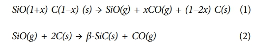
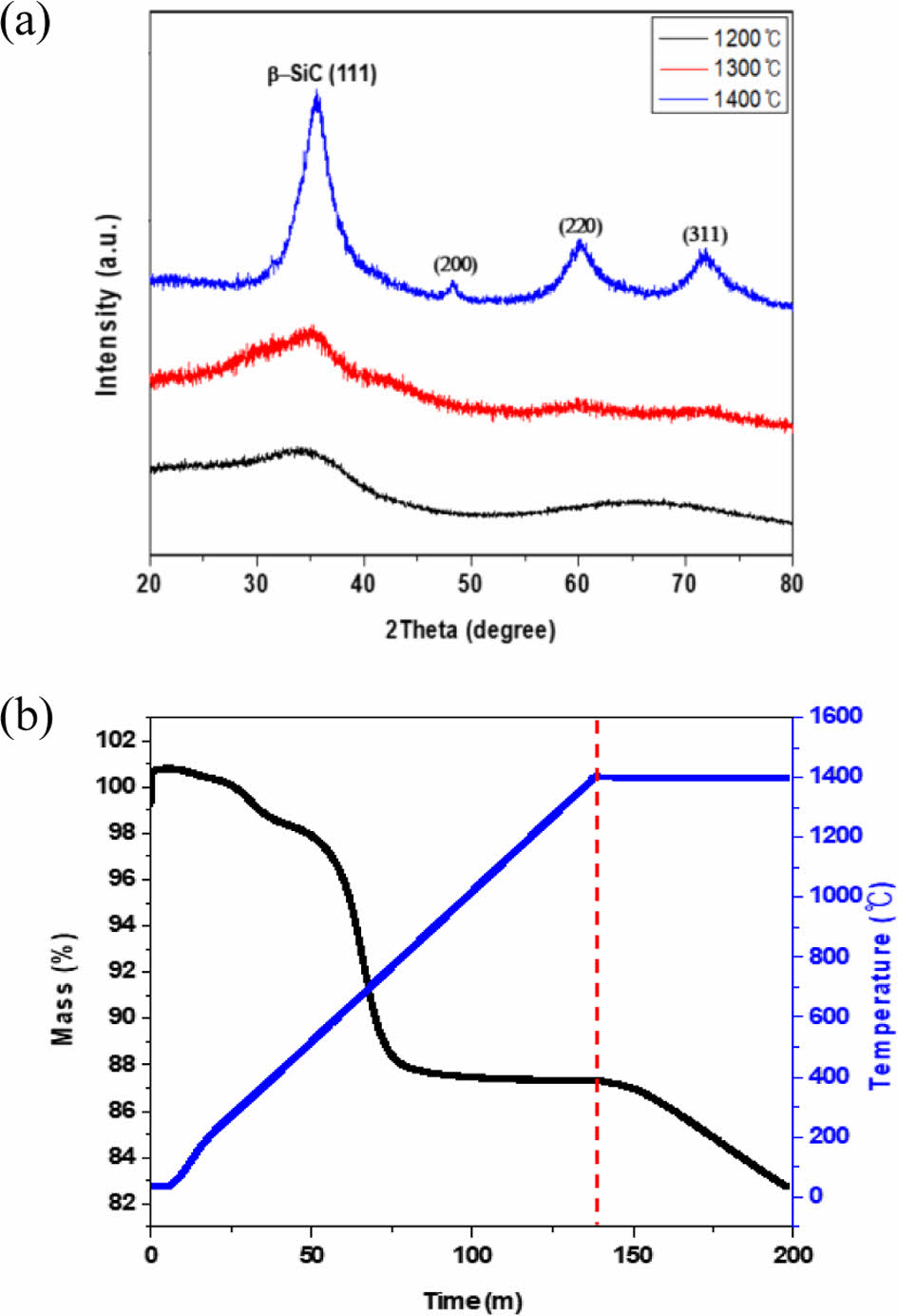
Fig. 2 shows the results of XRD analysis for various pyrolysis temperature values of Si-O-C fibers. A peak with a wide width for β-SiC (111) plane was observed at 1200°C. As the pyrolysis temperature increased, the broad peaks for the β-SiC (111), (220), (311), and (200) planes became sharp. It means that crystallization of the amorphous Si-O-C phase occurs as the pyrolysis temperature increases. The TGA analysis showed that the weight decreased from 100 to 82.72 wt% after pyrolysis at 1400oC for 1 hour. As shown in Equations (1) and (2), the amorphous Si-O-C structure slowly decomposes into nano-sized β-SiC crystals at a temperature of 1200°C or higher [25]. During the oxidation-curing process of the amorphous Si-O-C fiber, the decomposition occurs due to ambient oxygen. The weight loss at 1400°C was interpreted as the effect of SiO and CO gases generated by the secondary thermal decomposition of the SiOC matrix during the pyrolysis process.
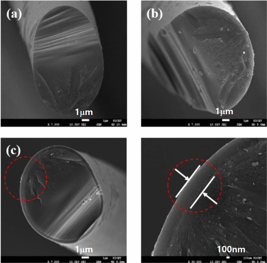
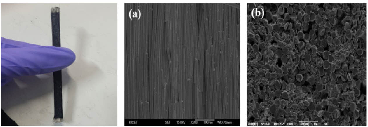
The decomposition behavior of the amorphous Si-O-C structure corresponding to the pyrolysis temperature was confirmed by the SEM analysis. As shown in Fig. 3, the fracture structure of the amorphous Si-O-C fiber pyrolyzed at 1200°C and 1300°C showed the same shape as that of the general amorphous ceramics; and mirror, mist, and hackle regions were observed on the fracture surface. A thin layer of 1 μm in size was observed on the fracture surface in the fiber pyrolyzed at 1400°C.
As the decomposition of the amorphous Si-O-C structure proceeds, a carbothermal reaction occurs at the fiber surface as shown in Equation (2), and a nano-sized β-SiC crystal structure is formed, which forms the thin 1 μm-sized layer on the fiber surface [16].
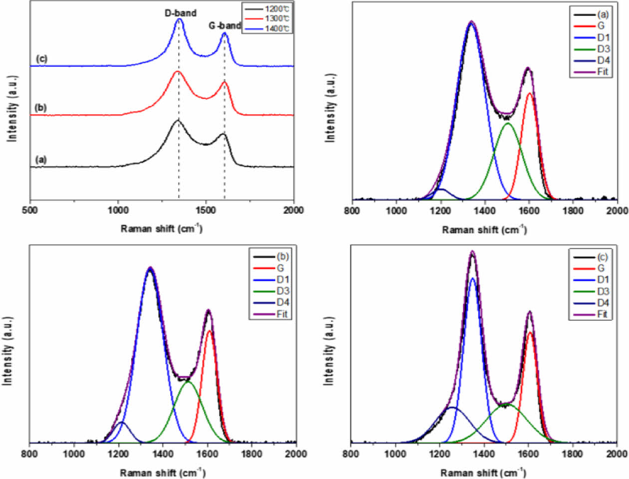
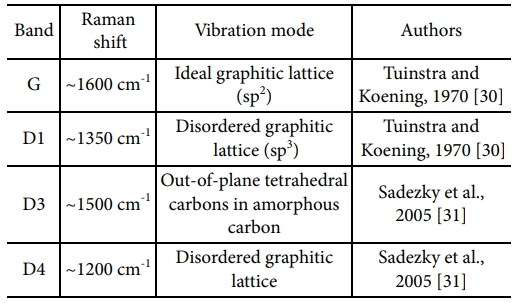
The G-band (1600 cm-1) region showing the graphitic C=C bond (sp2) structure on the surface of the amorphous Si-O-C fiber and the D-band (1350 cm-1) showing disordered carbon (sp3) structure such as defects and impurities were confirmed by Raman spectroscopy (Fig. 4) [26-29]. The relative binding ratio of the graphitic carbon structure on the fiber surface was calculated from the relative intensity ratio (ID/IG) of the D- and G-band peaks. The ID/IG values were 1.36, 1.31 and 1.43 for the pyrolysis temperatures of 1200°C, 1300°C, and 1400°C, respectively.
The carbon structure on the surface of the amorphous Si-O-C fiber was separated into an excess carbon layer, carbon nano-crystals dispersed on the amorphous Si-O-C, and amorphous structures using gaussian functions (Table 2). The G, D1, D3, and D4 peaks appeared at 1607 cm-1, 1347 cm-1, 1506 cm-1 and 1205 cm-1, respectively (Fig. 4).
The intensity of the amorphous carbon peak (D3) decreases as the pyrolysis temperature increases [16]. The TGA analysis performed previously suggested that the amorphous carbon structure on the amorphous Si-O-C fiber surface decomposed and was released in the form of CO gas as the pyrolysis temperature increased.
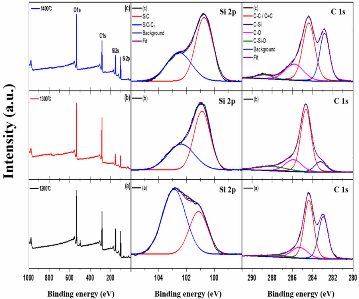
Fig. 5 shows the XPS profile corresponding to the pyrolysis temperature of the amorphous Si-O-C fibers. Si2p, Si2s, C1s and O1s peaks were formed and the Si2p and C1s peaks were separated into two and four peaks, respectively, using a Gaussian function [32]. The Si2p peak was divided into two bonding structures, Si-O-C (101.1 eV) and Si-C (102.8 eV), and the intensity of the SiC peak increased as the pyrolysis temperature increased. This is because the β-SiC crystal structure was formed during amorphous Si-O-C phase decomposition. The C1s peak was divided into four bonding structures: C–C/C = C (248.4 eV), C-Si (282.8 eV), C-Si-O (285.8 eV), and C=O (288.8 eV). The relative ratio of the graphitic carbon structure formed on the fiber surface was determined by calculating the area ratio occupied by the C–C/C = C (248.4 eV) bonding structure. The area ratios were 70.3, 75.5%, and 71.1% at pyrolysis temperatures of 1200°C, 1300°C, and 1400°C, respectively. First, the C–C/C =C (248.4 eV) bonding structure area ratio increased because of the excess carbon formed during phase decomposition of the amorphous Si-O-C on the surface at 1200–1300°C. The chemical combination of the SiO gas and excess carbon, as shown in Equation (2), leads to a decrease in the area ratio [33].
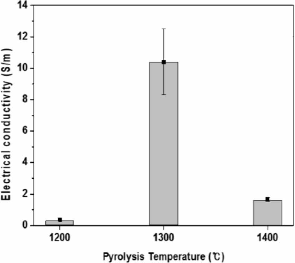
Fig. 6 shows the electrical conductivity values of amorphous Si-O-C fibers measured using the two-point probe method. This fiber is composed of a conductor with a carbon structure, nano-sized SiC semiconductor structure, amorphous Si-O-C structure, and nanopores of an insulator. The fiber’s conductivity at the pyrolysis temperature of 1200°C was measured to be an average of 0.37 ± 0.06 S/m. This is a result of poor electrical properties of the amorphous Si-O-C and carbon phases, which mainly form on the fiber surface. The fiber prepared at a pyrolysis temperature of 1300°C was measured to have an average conductivity of 10.41 ± 2.09 S/m. A graphitic carbon structure formed during the phase decomposition of the amorphous Si-O-C phase on the fiber surface, and a stable surface layer was maintained without weight reduction. In the case of the 1400°C pyrolyzed fiber, the electrical conductivity decreased to an average of 1.66 ± 0.12 S/m. The volume fractions of free carbon and SiC structure have a significant influence on the amorphous Si-O-C fiber conductivity. The volume fraction of free carbon in the amorphous Si-O-C fiber decreases owing to endogenous oxidation during the amorphous Si-O-C phase decomposition at 1400°C or higher, so the conductivity is related only to the SiC structure resistivity.
3.2 Evaluation of electrical heating properties of the Si-O-C fiber heating element
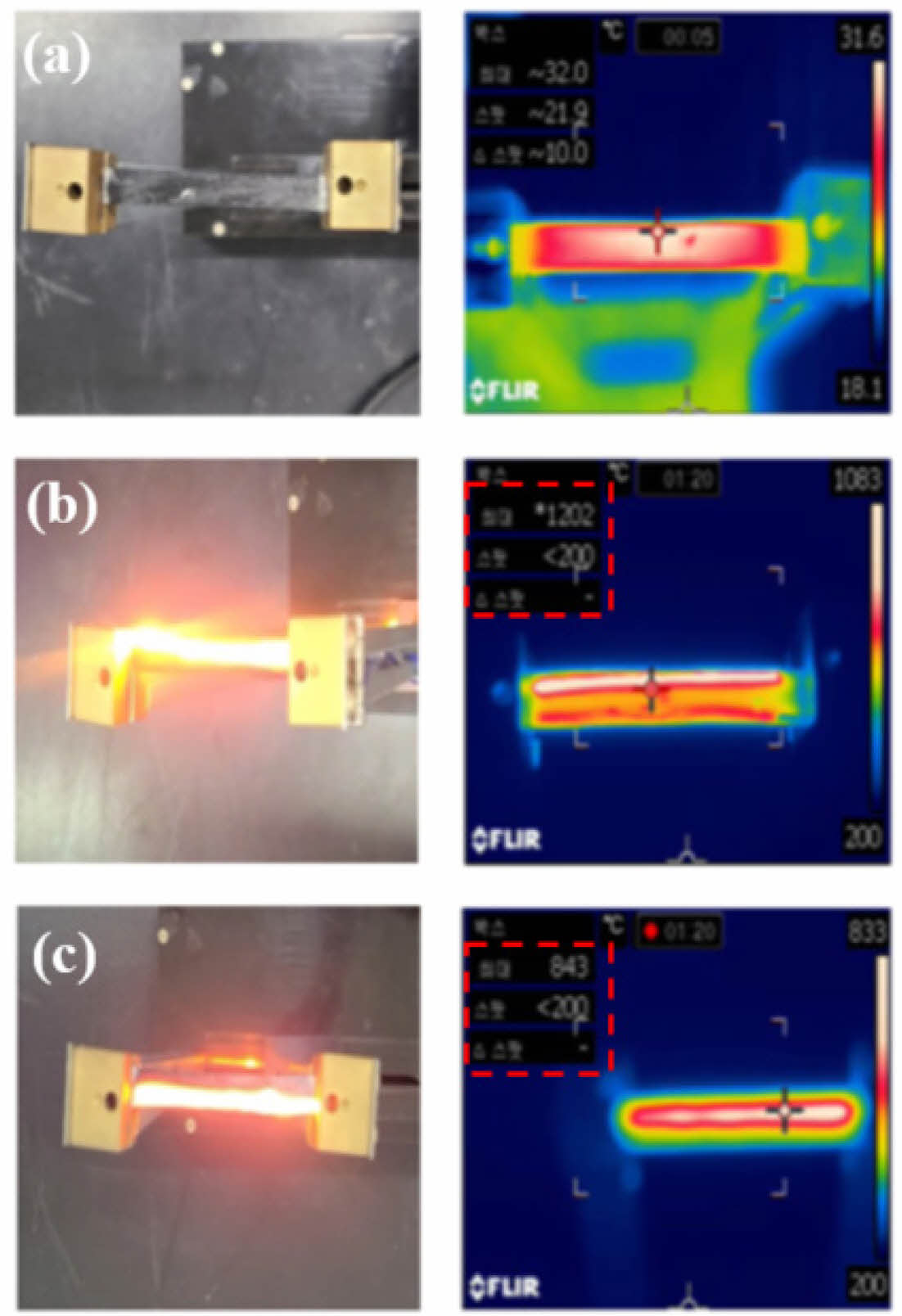
Fig. 7 shows SEM images of the stick-type amorphous Si-O-C fiber heating element. Although it had a relatively good fiber shape, an empty space was formed between the fibers. This is because a simple pressurization method was used to maintain the shape of the heating element during oxidation curing. The heat test results for the stick-type amorphous Si-O-C fiber heating element are shown in Fig. 8. The measurement started at 200°C, which is the lowest temperature value of the infrared camera. The test voltage was constantly maintained at 340 V. The heating element manufactured at a pyrolysis temperature of 1200°C did not generate heat because of the low electrical conductivity. The heating element at 1300oC took 80 seconds to reach the maximum measurement temperature range of 1200oC and consumed 276.95 W of power.
The difference in the electrical conductivity of the fibers manufactured at 1200°C and 1400°C was approximately 1S/m, but heat was generated in the case of the heating element manufactured at 1400°C. It reached 843oC within 80 seconds, and 188.74 W of power was consumed. In both the heating elements, less graphitic carbon was formed on the surface compared to the heating element manufactured at 1300°C. The heating element manufactured at 1400°C generated heat because of its structural resistivity of SiC and reduced graphitic carbon structure, unlike the one produced at 1200°C which had amorphous structural resistivity.
|
Fig. 2 (a) X-ray diffraction patterns and (b) thermogravimetry analysis of the Si-O-C fiber as a function of pyrolysis |
|
Fig. 3 Cross-sectional microstructure of the (a) 1200oC, (b) 1300oC, (c) 1400oC pyrolyzed Si-O-C fiber |
|
Fig. 4 Raman spectra of the (a) 1200oC, (b) 1300oC, (c) 1400oC pyrolyzed Si-O-C fiber and their four-peak fitting |
|
Fig. 5 XPS spectra of the (a) 1200oC, (b) 1300oC, (c) 1400oC pyrolyzed Si-O-C fiber |
|
Fig. 6 Electrical conductivity of the Si-O-C fiber |
|
Fig. 7 SEM image of the Si-O-C fiber heating element (a) surface, (b) cross section |
|
Fig. 8 Heating test image of the Si-O-C fiber heating element (a) 1200oC, (b) 1300oC, (c) 1400oC pyrolyzed |
Polycarbosilane fibers were prepared by melt spinning, and amorphous Si-O-C fibers and stick-type heating elements were manufactured through oxidation curing and pyrolysis processes. As the pyrolysis temperature increased, a change in peaks was observed in the XRD graph and was attributed to the growth of β-SiC crystals in the fibers. Raman spectroscopy and XPS analysis revealed graphitic carbon formation on the surface of the amorphous Si-O-C fiber at a pyrolysis temperature of 1300°C. This amorphous Si-O-C fiber (prepared at the pyrolysis temperature of 1300°C) displayed the highest conductivity at 10.41 ± 2.09 S/m. This result showed that the ratio of graphitic carbon formed on the fiber surface had a great influence on the electrical properties of the amorphous Si-O-C fibers. A stick-type amorphous Si-O-C fiber heating element was manufactured, and its heating characteristics were evaluated. The heating element with a pyrolysis temperature of 1300°C took 80 seconds to reach the maximum measurement temperature range of 1200oC with the power consumption of 276.98 W.
PCS: Polycarbosilane, SiC: Silicon Carbide, PDMS: polydimethylsilane, XRD: X-ray diffraction, TGA: thermos-gravimetric analysis, FE-SEM: field-emission scanning electron microscopy, XPS: X-ray photoelectron spectroscopy, TPP: two-point probe.
This work was supported by the Industrial Strategic Technology Development Program funded by the Ministry of Trade, Industry, and Energy (MOTIE, Korea) [Program Name: Development of semi-noncombustible protection product using economical SiC fiber mass production technology; Project No.: 20003890].
This resrearch was financially supported by the Institute of Civil Military Technology Cooperation funded by the Defense Acquisition Program Administration and Ministry of Trade, Industry and Energy of Korean government under grant No.21-CM-CE-03.
- 1. He, R., Fang, D., Wang, P., Zhang, X., and Zhang, R., “Electrical properties of ZrB2–SiC ceramics with potential for heating element applications,” Cermaic International, Vol. 40, No. 7, 2014, pp. 9549-9553.
-

- 2. Kim, T., and Chung, D.D., “Carbon fiber mats as resistive heating elements,” Carbon, Vol. 41, No. 12, 2003, pp. 2436-2440.
- 3. Cho, J.H., and Hwang, H.S., “Image processing technology for analyzing the heating state of carbon fiber surface heating element,” Journal of the Korea Academia-Industrial cooperation Society, Vol. 19, No. 2, 2018, pp. 683-688.
-
- 4. Joo, Y.J., and Cho, K.Y., “Fabrication and resistance heating properties of flexible SiC fiber rope as heating elements,” Carbon, Vol. 41, No. 12, 2003, pp. 2436-2440.
- 5. Sheehan, J.E., “Oxidation protection for carbon fiber composites,” Carbon, Vol. 27, No. 5, 1989, pp. 709-715.
-
- 6. Lamouroux, F., Bertrand, S., Pailler, R., Naslain, R., and Cataldi, M., “Oxidation-resistant carbon-fiber-reinforced ceramic-matrix composites,” Composite Science Technology, Vol. 59, No. 7, 1999, pp. 1073-1085.
-
- 7. Naslain, R.R., “SiC‐matrix composites: nonbrittle ceramics for thermo‐structural application,” International Journal of Applied Ceramic Technology, Vol. 2, No. 2, 2005, pp. 75-84.
-
- 8. Katoh, Y., Ozawa, K., and Shih, C., “Continuous SiC fiber, CVI SiC matrix composites for nuclear applications: Properties and irradiation effects,” Journal of Nuclear Materials, Vol. 448, No. 1-3, 2014, pp. 448-476.
-
- 9. Katoh, Y., Snead, L.L., and Henager Jr, C.H., “Current status and recent research achievements in SiC/SiC composites,” Journal of Nuclear Materials, Vol. 455, No. 1-3, 2014, pp. 387-397.
-
- 10. Yajima, S., Hayashi, J., and Omori, M., “Continuous silicon carbide fiber of high tensile strength,” Chemistry Letter, Vol. 4, No. 9, 1975, pp. 931-934.
-
- 11. Yajima, S., Okamura, K., Hayashi, J., and Omori, M., “Synthesis of continuous SiC fibers with high tensile strength,” Journal of the Amercan Ceramic Society, Vol. 59, No. 7-8, 1976, pp. 324-327.
-
- 12. Yajima, S., Hayashi, J., and Omori, M., “Development of a silicon carbide fiber with high tensile strength,” Nature, Vol. 261, 1976, pp. 683-685.
-
- 13. Yajima, S., Hasegawa, Y., Okamura, K., and Matsuzawa, T., “Development of high tensile strength silicon carbide fiber using an organosilicon polymer precursor,” Nature, Vol. 273, 1978, pp. 525-527.
-
- 14. Schilling Jr, C.L., Wesson, J.P., and Williams, T.C., “Polycarbosilane precursors for silicon carbide,” Journal of Polymer Science: Polymer Symposia. Vol. 70, No. 1, 1983, pp. 121-128.
-
- 15. Takeda, M., Sakamoto, J., Imai, Y., Ichikawa, H., and Ishikawa, T., “Properties of stoichiometric silicon carbide fiber derived from polycarbosilane,” Proceedings of the 18th Annual Conference on Composites and Advanced Ceramic Materials—A: Ceramic Engineering and Science Proceedings; 1994 Jan 1; Hoboken, NJ, USA: John Wiley & Sons, Inc. pp. 133-141.
-
- 16. Mah, T., Hecht, N.L., and McCullum, D.E., “Thermal stability of SiC fibers (Nicalon¢ç),” Journal of Materials Science, Vol. 19, No. 4, 1984, pp. 1191-1201.
-
- 17. Porte, L., and Sartre, A., “Evidence for a silicon oxycarbide phase in the Nicalon silicon carbide fiber,” Journal of Materials Science, Vol. 24, No. 1, 1989, pp. 271-275.
-
- 18. Maniette, Y., and Oberlin, A., “TEM characterization of some crude or air heat-treated SiC Nicalon fibers,” Journal of Materials Science, Vol. 24, No. 9, 1989, pp. 3361-3370.
-
- 19. Shin, D.G., Riu, D.H., Kim, Y., Kim, H.R., Park, H.S., and Kim, H.E., “Characterization of SiC fiber derived from polycarbosilanes with controlled molecular weight,” Journal of Korean Ceramic Society, Vol. 42, No. 8, 2005, pp. 593-598.
- 20. Chollon, G., Pailler, R., Canet, R., and Delhaes, P., “Correlation between microstructure and electrical properties of SiC-based fibers derived from organosilicon precursors,” Journal of European Ceramic Society, Vol. 18, No. 6, 1998, pp. 725-733.
-
- 21. Scholz, R., dos Santos Marques, F., and Riccardi, B., “Electrical conductivity of silicon carbide composites and fibers,” Journal of Nuclear Materials, Vol. 307, 2002, pp. 1098-1101.
-
- 22. Wang, D.Y., Song, Y.C., and Li, Y.Q., “Effect of composition and structure on specific resistivity of SiC fibers,” Transactions of Nonferrous Metals Society of China, Vol. 22, No. 5, 2012, pp. 1133-1139.
-
- 23. Mo, R., Yin, X., Li, M., Ye, F., Fan, X., and Cheng, L., “Relationship between microstructure and electromagnetic properties of SiC fibers,” Journal of American Ceramic Society, Vol. 103, No. 8, 2020, pp. 4352-4362.
-
- 24. Ding, D., Zhou, W., Zhang, B., Luo, F., and Zhu, D., Complex permittivity and microwave absorbing properties of SiC fiber woven fabrics,” Journal of Materials Science, Vol. 46, No. 8, 2011, pp. 2709-2714.
-
- 25. Cao, S., Wang, J., and Wang, H., “Formation mechanism of large SiC grains on SiC fiber surfaces during heat treatment,” CrystEngComm, Vol. 18, No. 20, 2016, pp. 3674-3682.
-
- 26. Sasaki, Y., Nishina, Y., Sato, M., and Okamura, K., “Raman study of SiC fibers made from polycarbosilane,” Journal of Materials Science, Vol. 22, No. 2, 1987, pp. 443-448.
-
- 27. Karlin, S., and Colomban, P., “Raman study of the chemical and thermal degradation of as-received and sol–gel embedded Nicalon and Hi‐Nicalon SiC fibers used in ceramic matrix composites,” Journal of Raman Spectroscopy, Vol. 28, No. 4, 1997, pp. 219-228.
-
- 28. Gouadec, G., Karlin, S., and Colomban, P., “Raman extensometry study of NLM202¢ç and Hi-Nicalon¢ç SiC fibers,” Composites, Part B, Vol. 29, No. 3, 1998, pp. 251-261.
-
- 29. Karlin, S., and Colomban, P., “Micro-Raman study of SiC fiber-oxide matrix reaction,” Composites, Part B, Vol. 29, No. 1, 1998, pp. 41-50.
-
- 30. Tuinstra, F., and Koenig, J.L., “Raman spectrum of graphite,” The Journal of Chemical Physics, Vol. 53, No. 3, 1970, pp. 1126-1130.
-
- 31. Sadezky, A., Muckenhuber, H., Grothe, H., Niessner, R., and Pöschl, U., “Raman microspectroscopy of soot and related carbonaceous materials: Spectral analysis and structural information,” Carbon, Vol. 43, No. 8, 2005, pp. 1731-1742.
-
- 32. Chastain, J., and King Jr, R.C., Handbook of X-ray photoelectron spectroscopy. Perkin-Elmer Corporation, 40, 1992, 221.
- 33. Le Coustumer, P., Monthioux, M., and Oberlin, A., “Understanding Nicalon¢ç fiber,” Journal of European Ceramic Society, Vol. 11, No. 2, 1993, pp. 95-103.
-
 This Article
-
2024; 37(4): 330-336
Published on Aug 31, 2024
- 10.7234/composres.2024.37.4.330
- Received on May 24, 2024
- Revised on Jul 6, 2024
- Accepted on Jul 18, 2024
Services
- Abstract
1. introduction
2. experiments
3. results and discussion
4. conclusions
abbreviations
- Acknowledgements
- References
- Full Text PDF
Shared
Correspondence to
- Dong-Geun Shin
-
Aerospace Convergence Materials Center, Korea Institute of Ceramic Engineering & Technology, Jinju 52851, Korea
- E-mail: dgshin73@kicet.re.kr
Gangnam Mirae Tower, Suite 601, 174 Saimdang-ro, Seocho-gu, Seoul 06627, South Korea
Tel: +82-2-598-1550 Fax: +82-2-598-1557 E-mail: composites@kscm.re.kr