- Super Duplex Stainless Steel Matrix Composites with High Strength and Favorable Ductility Achieved Through Laser Powder Bed Fusion and Powder Mixture
Yongjian Fang*, Yali Zhang*, Jonghwan Suhr*†
* School of Mechanical Engineering, Sungkyunkwan University, Suwon 16419, Korea
This article is an open access article distributed under the terms of the Creative Commons Attribution Non-Commercial License (http://creativecommons.org/licenses/by-nc/4.0) which permits unrestricted non-commercial use, distribution, and reproduction in any medium, provided the original work is properly cited.
:In order to evade the premature failure of super duplex stainless steels (SDSSs) in some harsh environments, the increase of their mechanical properties is a promising approach. In this study, based on the laser powder bed fusion (LPBF) technique, SDSS matrix composites without post heat treatment were fabricated by using the powder mixture of SDSSs, super austenitic stainless steels (SASSs) and micron-sized TiC particles. Many in-situ TiCxNy nanoparticles were found to be formed by using micron-sized TiC particles in as-built composites, and both fine ferrite and austenite grains were generated. The as-built composites exhibited an excellent combination of high ultimate tensile strength (UTS) (~1066 MPa) and good uniform elongation (UE) (~15.6%), showing a better mechanical property compared with other reported LPBF-fabricated SDSSs, which was mainly attributed to the fine grain, Orowan and dislocation strengthening mechanisms. In particular, the successful fabrication of SDSS matrix composites can set the stage for producing high-performance metallic parts via LPBF technique.
Keywords: Laser powder bed fusion, Super duplex stainless steels, Super austenitic stainless steels, Metal matrix composites, Mechanical properties
Although super duplex stainless steels (SDSSs) are famous for their good mechanical properties and favorable corrosion resistance, the premature failure of them can be found in certain extreme environments due to their limited strength [1]. It is necessary to enhance their mechanical properties to solve this problem, and it was proved that the fabrication of SDSS matrix composites based on laser powder bed fusion (LPBF) technique was a viable method [2]. By utilizing LPBF technique and certain ceramic particles, some complex metallic parts with fine grains were found to be successfully fabricated, achieving the improvement of mechanical properties [2,3].
For instance, tungsten carbide (WC) particles were employed as reinforcements to strengthen IN718 alloys based on the LPBF technique, and it was found that the hardness of materials could be effectively increased by about 38% [4]. Particularly, it was proved that the strength of LPBF-fabricated 316L SSs could be enhanced by using in-situ formed TiC nanoparticles induced by the melting of micron-sized TiC particles, and a good ductility could also be maintained [5]. However, considering the ultra-high cooling rate during the LPBF process, a balanced ferritic-austenitic microstructure cannot be obtained for LPBF-fabricated SDSSs [6], and a post heat treatment should be applied.
In this study, in order to achieve the fabrication of LPBF-fabricated SDSSs without post heat treatment, super austenitic stainless steel (SASS) powder will be added into SDSS powder to produce more austenite phase. In addition, micron-sized TiC particles will be employed to in-situ generate some nanoparticles to significantly enhance the mechanical properties of SDSSs. By optimizing relevant process parameters, a SDSS matrix composite with excellent mechanical properties was acquired, and relevant strengthening mechanisms were discussed. In particular, this investigation is capable of proving a groundwork for developing high-performance SDSS structural parts with complex geometry.
2.1 Materials and LPBF Process
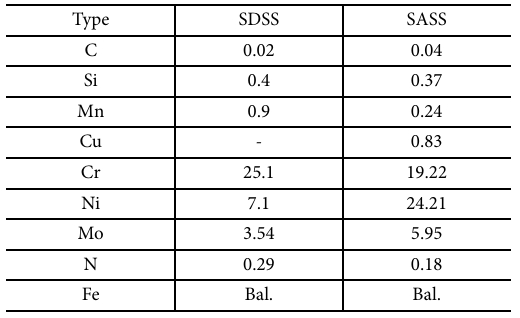
The gas atomized SAF 2507 SDSS powder (15-53 μm) was bought from a powder manufacturer (Sandvik Osprey Ltd.). For SASS powder (15-53 μm), it was provided by a powder supplier (CHENGDU HUAYIN POWDER TECHNOLOGY CO., LTD). The chemical composition of the two types of powder is listed in Table 1. It was reported that sub-micron TiC particles were prone to be melted to produce nanoparticles during LPBF process, while the agglomeration of sub-micron TiC particles with small size could be easily observed during mixing [3]. Therefore, micron-sized TiC particles and nearly sub-micron-sized TiC particles were used as reinforcements. The applied micron-sized TiC particles have two types of size (~1 μm and 5-25 μm), and the powder mixture of 69 wt.% SDSSs, 29 wt.% SASSs, 1 wt.% TiC (5-25 μm) and 1 wt.% TiC (~1 μm) was obtained by employing a Inversina Tumbler Mixer (rotation speed of 80 rpm and mixing time of 40 mins).
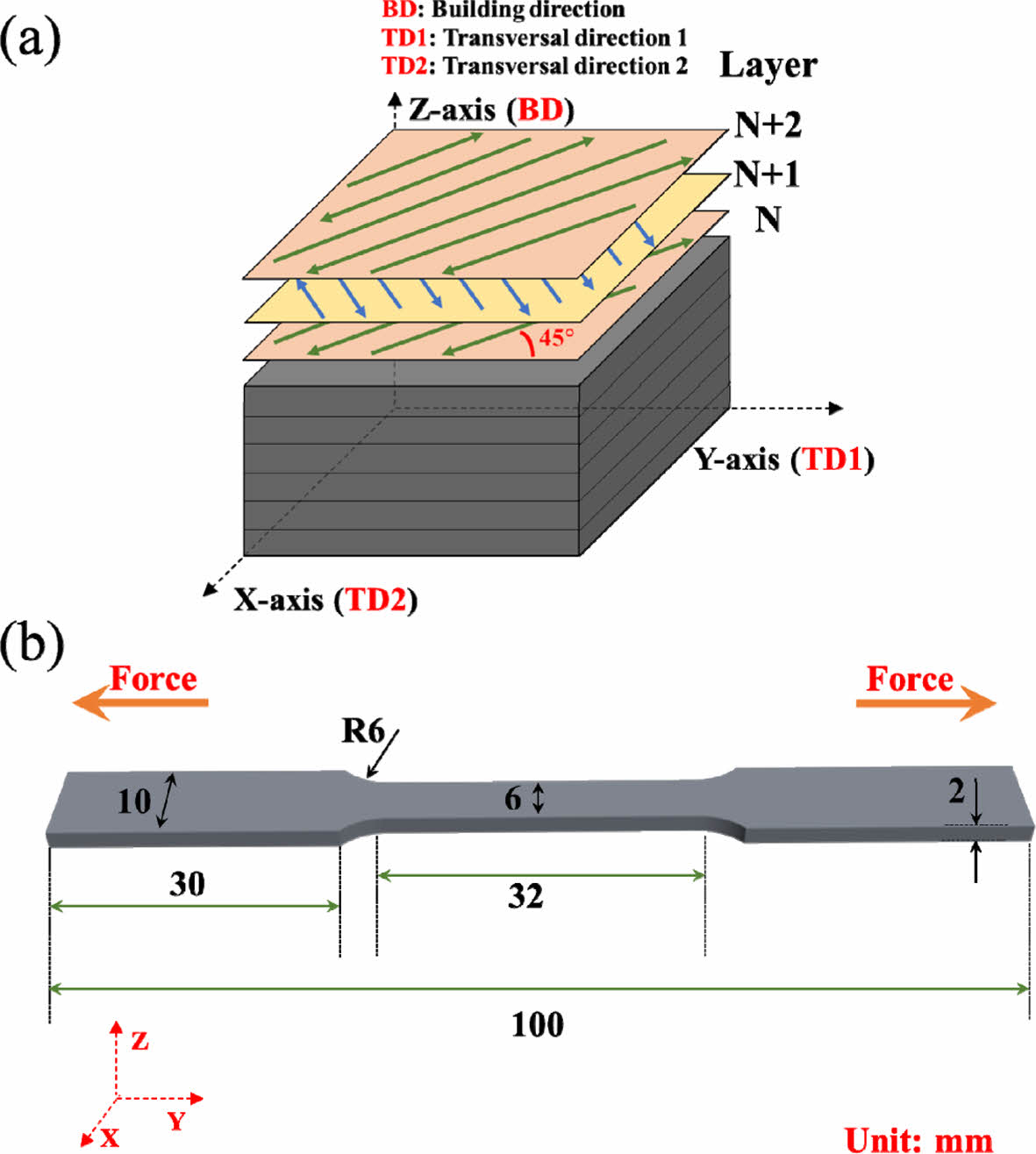
A LPBF machine with a single mode fiber laser of 500 W was employed to conduct the printing of materials, and the N2 with a high purity was used as the protective gas during printing. In order to balance the microstructure of materials on X-Z and Y-Z planes, a 45° deviation was chosen between the X/Y-axis and laser scanning direction (bidirectional laser scanning), as shown in Fig. 1a. To inhibit the formation of textures, a laser rotation angle of 90° was set between continuous building layers. In addition, the build platform was preheated to about 80°C to alleviate the generation of residual stress.
Based on our previous optimized parameters for LPBF-fabricated DSSs [2], the layer thickness (t) and hatch spacing (h) were determined to be 40 μm and 100 μm, respectively, and 5 process parameters were designed through the combination of laser power (P) of 255 W and several scanning speed (v) (990, 860, 730, 600 and 470 mm/s). According to these designed process parameters, the laser volumetric energy density (η) of samples can be calculated through formula (1) [7].

2.2 Microstructure Characterization and Tensile Tests
After obtaining the metallographic samples by grinding and polishing, a 30 vol% KOH solution was employed to electro-etch (4 V; 10 seconds) these samples to characterize their microstructure. An X-ray diffraction (XRD) spectrometer (Cu-Kα radiation) was used for identifying the phase of samples, and a scanning range of 35-95° (2theta) and a step size of 0.02° were set. The optical microscope (OM) as well as scanning electron microscope (SEM) equipment were applied to further analyze the microstructure of samples. In order to investigate the microstructure in detail, the electron back-scatter diffraction (EBSD) characterization (step size: 0.2 μm) was carried out. To evaluate the printing quality of samples, the Archimedes method was used for getting the sample density. The mechanical properties of samples were assessed by conducting the room-temperature tensile testing via an electronic universal testing equipment with an extensometer. As shown in Fig. 1b, the tensile direction of samples is parallel with their transverse direction (TD), and a crosshead velocity of 0.25 mm/min was set. According to the ASTM E 8M-04 standard [8], three horizontal tensile samples (gauge dimension: 32 × 6 × 2 mm3) were tested.
|
Fig. 1 (a) The applied scanning strategy for as-built composites, (b) the schematic showing the LPBF-fabricated tensile samples |
3.1 The Optimization of Process Parameters of As-built Composites
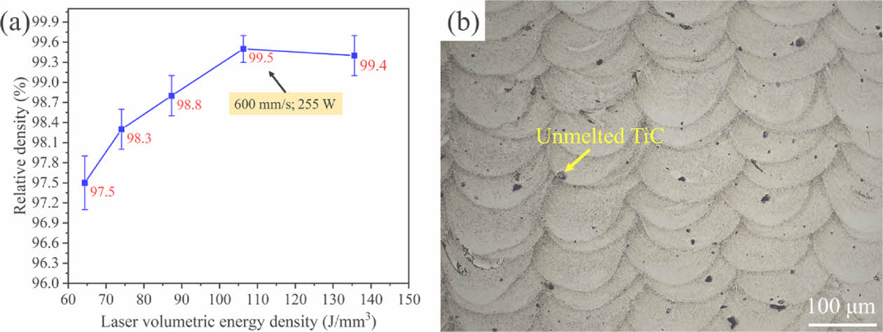
When relatively low energy density is employed, some pores induced by the lack of fusion are prone to be generated [9], resulting in the low relative density of samples (Fig. 2a). With the increase of energy density, it can be found that the relative density is gradually enhanced, which is mainly attributed to the increase in the overlap depth between consecutive molten pools [2]. Therefore, when the energy density values of 106 and 135.6 J/mm3 are used, the samples with high densification can be obtained. However, considering the coarsening behavior of grains under a high energy density, the process parameter with a laser power of 255 W and scanning speed of 600 mm/s is confirmed to be the optimal one. As shown in Fig. 2b, some unmelted TiC particles can be found, and coarse epitaxial columnar grains are not observed, indicating that the grains of as-built composites can be effectively refined.
3.2 The Microstructure Analysis of As-built Composites
As shown in Fig. 3a, many fine particles are formed in as-built composites, and these particles are confirmed to be in-situ formed TiCxNy nanoparticles based on our previous studies [2]. The existence of these nanoparticles plays an important role in the refinement of matrix strains. The XRD characterization is employed to confirm the phase of as-built composites, as shown in Fig. 3b. It can be found that the microstructure is mainly comprised of austenite and ferrite phases. By using the Rietveld method and MAUD software, the amount of austenite and ferrite are estimated to be approximate 71 wt.% and 29 wt.%, respectively. The unmelted micron-sized TiC particles and TiCxNy nanoparticles are not detected by XRD characterization due to their low content. Hence, the XRD results can confirm that a LPBF-fabricated SDSS matrix composite is directly obtained in this study.
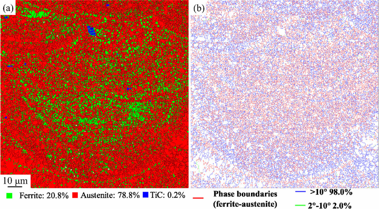
The EBSD characterization is employed to further analyze the microstructure of as-built composites. As shown in Fig. 4a, the phase map indicates that the microstructure is composed of 78.8% austenite and 20.8% ferrite. Compared with the phase ratio obtained by XRD characterization, less ferrite phase is confirmed by EBSD characterization, which is mainly attributed to the fact that some very fine ferrite grains cannot be detected by EBSD characterization. In addition, some unmelted TiC particles are found to be remained. Compared with other reported LPBF-fabricated SDSSs nearly composed of ferrite phase [10], more austenite grains are proved to be formed in as-built composites, demonstrating that the effectiveness of the applied method.
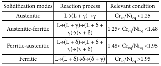
According to the Creq/Nieq value and some solidification modes of ASSs (Table 2), the solidified microstructure of ASSs can be estimated, and the values of Nieq and Creq can be obtained through equations (2-3) [11].


For equations (2-3), the Creq/Nieq value is related to the weight percent (wt.%) of elements. As shown in Table 1, SASSs have a high content of Ni element, and their Creq/Nieq value is calculated to be about 1 by equations (2-3), indicating that a full austenitic microstructure should be formed. Furthermore, the mixing and reaction between SASSs as well as SDSSs with a higher content of Cr element can decrease the Ni content within certain areas of molten pools, rendering the increase in Creq/Nieq value. Based on Table 2, if the Creq/Nieq value is increased a little, an austenitic-ferritic solidification mode can be formed. The austenite grains will be produced first, and then some ferrite grains can be generated along the grain boundaries of austenite. If the Creq/Nieq value is increased a lot, a ferritic-austenitic solidification mode can occur. After the primary δ-ferrite grains are formed, some intergranular austenite grains are able to be formed. In addition, due to the intensive Marangoni convection, some unmixed SDSS melts can be remained to form isolated ferrite grains after solidification. Therefore, more ferrite grains can be formed in as-built composites compared with other reported LPBF-fabricated SDSSs [10].
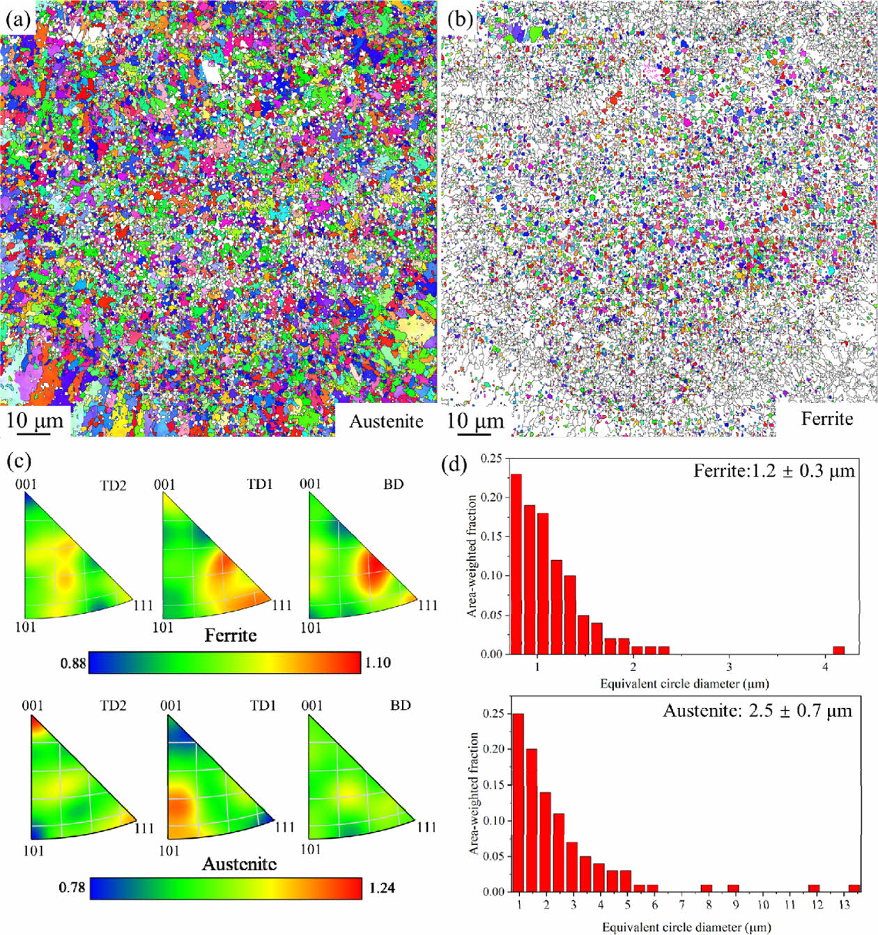
Based on the grain boundary distribution map (Fig. 4b), in addition to the formation of lots of phase boundaries and high-angle grain boundaries (HAGBs), a few low-angle grain boundaries (LAGBs) can be observed, and the formation of these LAGBs is mainly caused by the dislocation rearrangement [12]. Particularly, as shown in Fig. 5a-b, the orientation maps of the inverse pole figures (IPFs) of phases in BD can prove that the random grain orientation is generated for both ferrite and austenite grains. Furthermore, such a random grain orientation can also be identified by the IPFs of both phases (maximum texture indexes < 1.3), as shown in Fig. 5c. Therefore, no obvious textures are formed in as-built composites, and good isotropic mechanical properties are anticipated to be obtained.
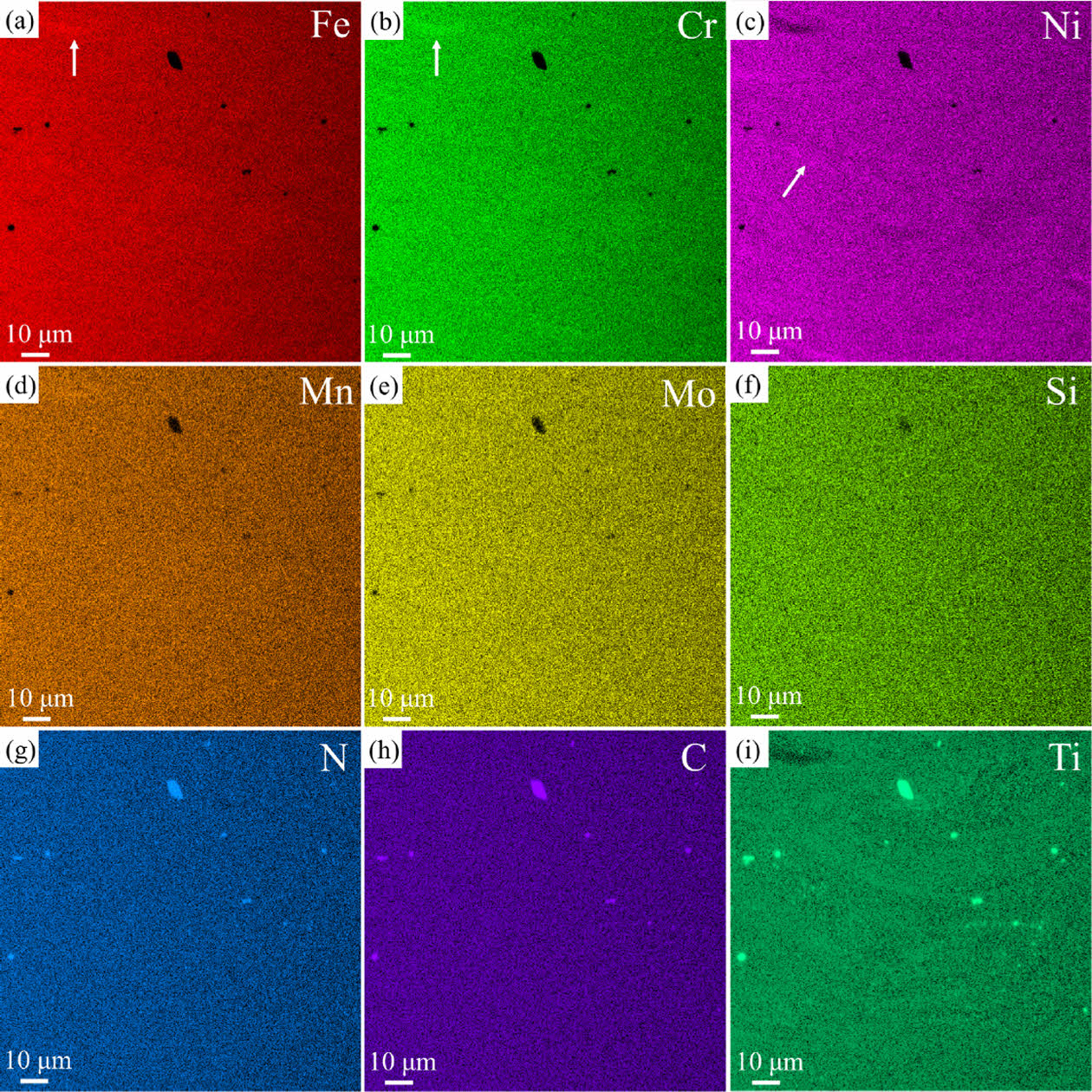
As shown in Fig. 6, the EDS characterization of as-built composites exhibits the details of elemental distribution. The slight element segregation can be found, such as Fe, Cr and Ni elements, as indicated by the white arrows. Based on the chemical composition listed in Table 1, it can be found that there is an obvious difference in the content of Ni and Cr elements between SDSSs and SASSs. During LPBF process, certain unmixed melts can be generated due to the insufficient melt flow. Under the strong Marangoni convection induced by LPBF process, these unmixed melts are prone to be moved towards the center of molten pools. Subsequently, the rapid solidification of them can occur, resulting in some remnant unmixed melts to produce some areas with slight element segregation [9].
According to the distribution of C, N and Ti elements, some unmelted TiC particles can be found. However, the existence of N elements is detected in these TiC particles. On the one hand, this phenomenon can be attributed to the detection limitation of EDS characterization for N elements. On the other hand, the relatively high temperature induced by LPBF process is capable of facilitating the reaction between unmelted TiC particles and N elements, generating some TiCxNy phase in unmelted TiC particles [13].
3.3 The Mechanical Properties of As-built Composites
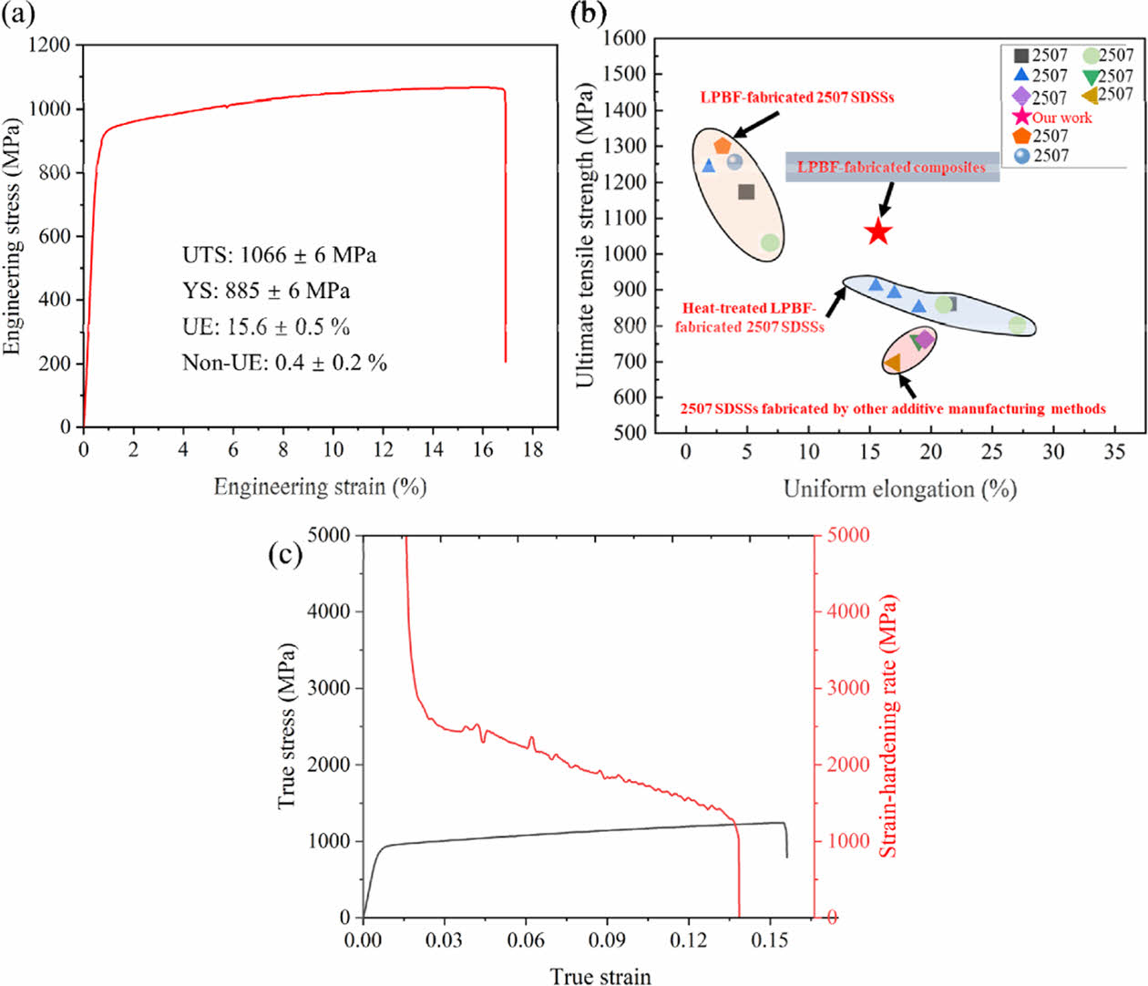
In order to assess the mechanical properties of as-built composites, their tensile tests are conducted, and the results are shown in Fig. 7a. It can be found that not only a high ultimate tensile strength (UTS) is obtained, but also a favorable uniform elongation (UE) can be acquired. In particular, in comparison with some reported LPBF-fabricated SDSSs as well as heat-treated LPBF-fabricated SDSSs, the as-built composites obtained in this study exhibit an excellent combination of UTS and UE, demonstrating the achievement of good mechanical properties, as shown in Fig. 7b. The true stress-strain curve and the strain hardening rate curve as a function of true strain are exhibited in Fig. 7c. It can be found that the strain hardening rate of as-built composites is slowly decreased with the increase of true strain after the true strain surpasses around 3%, indicating that the as-built composites possess a good strain hardening capability.
3.4 Discussion
For the LPBF-fabricated DSSs obtained by using the powder mixture of DSS and ASS powder, coarse ferrite grains were found to be formed, and the distribution of austenite and ferrite was not homogeneous. The UTS and UE of LPBF-fabricated DSSs were ~763 MPa and ~21%, respectively [22]. Although the UE of as-built composites obtained in this study is reduced to ~15.6% compared to LPBF-fabricated DSSs obtained in other works, their UTS is significantly increased to 1066 MPa.
According to the data exhibited in Fig. 7b, the as-built composites are proved to have better tensile properties compared with some DSSs, and it is necessary to discuss relevant strengthening mechanisms. First, with the cooling of molten pools, some Ti and C elements decomposed by the TiC particles can combine and react with N elements, forming TiCxNy nanoparticles. Subsequently, these nanoparticles can provide numerous heterogeneous nucleation sites for the matrix (ferrite or austenite), and the nucleation of matrix grains can be facilitated [2]. Therefore, the growth of matrix grains is hampered by the competitive growth between grains as well as the pinning effect of grain boundaries provided by TiCxNy nanoparticles, inducing the grain refinement of as-built composites.
As shown in Fig. 5d, the fine ferrite (~1.2 μm) and austenite (~2.5 μm) grains are found to be produced, and the movement of dislocations can be impeded by grain boundaries during the deformation process, rendering the improvement in the strength of materials [3]. According to the following equation, the contribution of fine grain strengthening to the increase in yield strength (σGR) can be assessed.

where σ0 represents the yield strength of a single crystal, focusing solely on the effect of solid solution strengthening, d denotes the value of average grain size, and k represents a constant which is related to the materials.
Second, it was proved that the existence of TiCxNy nanoparticles could pin and inhibit the movement of dislocations to trigger the Orowan strengthening effect [23]. Therefore, a significant strength increment can be achieved by this type of strengthening mechanism. Third, owing to the difference in thermal expansion coefficient between the reinforced particles and matrix, some additional dislocations can be generated during the solidification [3]. Subsequently, the improvement of dislocation density can be achieved, which can further enhance the strength of materials based on the dislocation strengthening mechanism. Finally, well-bonded interfaces can be formed between the reinforced particles and matrix. Subsequently, a load transfer from the matrix grains to reinforced particles can occur during deformation, enhancing the strength of materials. However, such a strengthening effect is not obvious compared to other strengthening mechanisms.
Accordingly, the high strength of as-built composites is mainly attributed to the above-mentioned four strengthening mechanisms. However, it should be noted that as-built composites also exhibit a good ductility, and there are two main factors. On the one hand, as the plastic deformation is increased, the quantity of grains with slip directions and planes aligned in the high shear stress direction can be enhanced through the formation of numerous fine grains, thereby improving the ductility of materials [24]. On the other hand, during the deformation of as-built composites, those TiCxNy nanoparticles have the capability of initiating, dragging and pining dislocations, increasing their strain hardening rate and resulting in the simultaneous improvement of strength and UE [25].
|
Fig. 2 (a) The relative density of as-built composites at different process parameters, (b) the optical micrograph of as-built composites at the optimal process parameter |

|
Fig. 3 (a) The SEM image of as-built composites, (b) the XRD pattern of as-built composites |
|
Fig. 4 (a) The phase map of as-built composites on Y-Z plane, (b) the corresponding grain boundary (GB) misorientation map |
|
Fig. 5 (a) The orientation map of the IPF of austenite in BD, (b) the orientation map of the IPF of ferrite in BD, (c) the IPFs of ferrite and austenite, (d) the distribution of the grain size of ferrite and austenite |
|
Fig. 6 The EDS characterization of as-built composites at the optimal process parameter |
|
Fig. 7 (a) The engineering stress-strain curve of as-built composites obtained in this study, (b) an Ashby plot showing the UTS and UE of as-built composites obtained in this study and DSSs from literatures [14-21], (c) true stressstrain/strain hardening rate curves of as-built composites |
|
Table 2 The solidification modes and conditions regarding the fusion welding of ASSs (L: liquid; γ: austenite; δ: hightemperature ferrite) |
The enhancement of the mechanical properties of SDSSs is able to impede the cracking of SDSSs in certain extreme environments. To efficiently achieve the increase of their mechanical properties, based on laser powder bed fusion (LPBF) technique, the micron-sized TiC particles were employed to generate TiCxNy nanoparticles, and the SASS powder was added to form more austenite phase. Therefore, in this work, a SDSS matrix composite was successfully obtained without post heat treatment. Many fine ferrite and austenite grains were found to be formed, which made an important contribution to the increase of mechanical properties. In comparison with other reported LPBF-fabricated SDSSs, an excellent combination of high UTS (~1066 MPa) and good UE (~15.6%) was found to be achieved. In addition to fine grain strengthening, Orowan and dislocation strengthening mechanisms could also improve the mechanical properties of materials.
This work was supported by the National Research Foundation of Korea (NRF) grant funded by the Korea government (MSIT) (No. 2022R1A2C3011968).
- 1. Paijan, L.H., Berhan, M.N., Adenan, M.S., Yusof, N.F.M., and Haruman, E., “Structural Development of Expanded Austenite on Duplex Stainless Steel by Low Temperature Thermochemical Nitriding Process,” Advanced Materials Research, Vol. 576, 2012, pp. 260-263.
-

- 2. Fang, Y., Kim, M.-K., Zhang, Y., Kim, T., No, J., and Suhr, J., “A New Grain Refinement Route for Duplex Stainless Steels: Micro-duplex Stainless Steel Matrix Composites Processed by Laser Powder Bed Fusion,” Materials Science and Engineering: A, Vol. 881, 2023, pp. 145351.
-

- 3. Fang, Y., Kim, M.-K., Zhang, Y., Duan, Z., Yuan, Q., and Suhr, J., “Particulate-reinforced Iron-based Metal Matrix Composites Fabricated by Selective Laser Melting: A Systematic Review,” Journal of Manufacturing Processes, Vol. 74, 2022, pp. 592-639.
-

- 4. Gao, Y., Chen, H., Zhou, J., Tian, W., Nie, H., Wang, W., and Liang, J., “Microstructures and Wear Behaviors of WC Particle Reinforced Nickel-based Composites Fabricated by selective laser melting,” Journal of Manufacturing Processes, Vol. 95, 2023, pp. 291-301.
-

- 5. Zhai, W., Zhou, W., and Nai, S.M.L., “In-situ Formation of TiC Nanoparticles in Selective Laser Melting of 316L with Addition of Micronsized TiC Particles,” Materials Science and Engineering: A, Vol. 829, 2022, pp. 142179.
-

- 6. Haghdadi, N., Ledermueller, C., Chen, H., Chen, Z., Liu, Q., Li, X., Rohrer, G., Liao, X., Ringer, S., and Primig, S., “Evolution of Microstructure and Mechanical Properties in 2205 Duplex Stainless Steels during Additive Manufacturing and Heat Treatment,” Materials Science and Engineering: A, Vol. 835, 2022, pp. 142695.
-

- 7. DebRoy, T., Wei, H.L., Zuback, J.S., Mukherjee, T., Elmer, J.W., Milewski, J.O., Beese, A.M., Wilson-Heid, A., De, A., and Zhang, W., “Additive Manufacturing of Metallic Components-process, Structure and Properties,” Progress in Materials Science, Vol. 92, 2018, pp. 112-224.
-

- 8. ASTM E 8M-04 Standard Test Methods for Tension Testing of Metallic Materials, American Society for Testing and Materials, USA, 2004.
-

- 9. Fang, Y., Zhang, Y., Kim, M.-K., Kim, H.-I., No, J., Duan, Z., Yuan, Q., and Suhr, J., “An Austenite-rich Composite of Stainless Steels with High Strength and Favorable Ductility via Selective Laser Melting of a Powder Mixture,” Materials Science and Engineering: A, Vol. 855, 2022, pp. 143891.
-

- 10. Zhang, D., Liu, A., Yin, B., and Wen, P., “Additive Manufacturing of Duplex Stainless Steels - A Critical Review,” Journal of Manufacturing Processes, Vol. 73, 2022, pp. 496-517.
-

- 11. Fu, J.W., Yang, Y.S., Guo, J.J., and Tong, W.H., “Effect of Cooling Rate on Solidification Microstructures in AISI 304 Stainless Steel,” Materials Science and Technology, Vol. 24, 2008, pp. 941-944.
-

- 12. AlMangour, B., Grzesiak, D., and Yang, J.-M., “Nanocrystalline TiC-reinforced H13 Steel Matrix Nanocomposites Fabricated by Selective Laser Melting,” Materials & Design, Vol. 96, 2016, pp. 150-161.
-

- 13. Zhang, Y., Fang, Y., Kim, M.-K., Duan, Z., Yuan, Q., Oh, E., and Suhr, J., “In-situ TiCxNy Nanoparticle Reinforced Crack-free CoCrFeNi Medium-entropy Alloy Matrix Nanocomposites with High Strength and Ductility via Laser Powder Bed Fusion,” Composites Part B: Engineering, Vol. 273, 2024, 111237.
-

- 14. Jiang, D., Birbilis, N., Hutchinson, C.R., and Brameld, M., “On the Microstructure and Electrochemical Properties of additively Manufactured Duplex Stainless Steels Produced Using Laser-powder Bed Fusion,” Corrosion, Vol. 76, 2020, pp. 871-883.
-

- 15. Becker, L., Boes, J., Lentz, J., Cui, C., Steinbacher, M., Li, Y., Fechte-Heinen, R., Theisen, W., and Weber, S., “Influence of Annealing Time on the Microstructure and Properties of Additively Manufactured X2CrNiMoN25-7-4 Duplex Stainless Steel: Experiment and Simulation,” Materialia, Vol. 28, 2023, 101720.
-

- 16. Kunz, J., Boontanom, A., Herzog, S., Suwanpinij, P., Kaletsch, A., and Broeckmann, C., “Influence of Hot Isostatic Pressing Post-treatment on the Microstructure and Mechanical Behavior of Standard and Super Duplex Stainless Steel Produced by Laser Powder Bed Fusion,” Materials Science and Engineering: A, Vol. 794, 2020, 139806.
-

- 17. M Brázda, P.S., Rzepa, S., Melzer, D., and Vavřík, J., “Effect of Heat Treatment on Mechanical Properties of Duplex Steel SAF 2507 Manufactured by DED,” IOP Conference Series: Materials Science and Engineering, Vol. 1178, 2021, 012008.
-

- 18. Mulhi, A., Dehgahi, S., Waghmare, P., and Qureshi, A.J., “Process Parameter Optimization of 2507 Super Duplex Stainless Steel Additively Manufactured by the Laser Powder Bed Fusion Technique,” Metals, Vol. 13, 2023, 725.
-

- 19. Roos, S., Botero, C., and Rännar, L.-E., “Electron Beam Powder Bed Fusion Processing of 2507 Super Duplex Stainless Steel. As-built Phase Composition and Microstructural Properties,” Journal of Materials Research and Technology, Vol. 24, 2023, pp. 6473-6483.
-

- 20. Salvetr, P., Školáková, A., Melzer, D., Brázda, M., Duchoň, J., Drahokoupil, J., Svora, P., Msallamová, Š., and Novák, P., “Characterization of Super Duplex Stainless Steel SAF2507 Deposited by Directed Energy Deposition,” Materials Science and Engineering: A, Vol. 857, 2022, 144084.
-

- 21. Xie, C., Li, B., Liu, G., Liu, J., Ying, H., Li, D., Wang, S., and Wang, L., “Study on the Effect of Solution Treatment on Mechanical and Corrosion Properties of SAF 2507 DSS Produced by LPBF,” Journal of Materials Research and Technology, Vol. 26, 2023, pp. 2070-2081.
-

- 22. Kohler, M.L., Kunz, J., Herzog, S., Kaletsch, A., and Broeckmann, C., “Microstructure Analysis of Novel LPBF-processed Duplex Stainless Steels Correlated to Their Mechanical and Corrosion Properties,” Materials Science & Engineering A, Vol. 801, 2021, 140432.
-

- 23. Saba, F., Zhang, F., Liu, S., and Liu, T., “Reinforcement Size Dependence of Mechanical Properties and Strengthening Mechanisms in Diamond Reinforced Titanium Metal Matrix Composites,” Composites Part B: Engineering, Vol. 167, 2019, pp. 7-19.
-

- 24. Zhai, W., Zhu, Z., Zhou, W., Nai, S.M.L., and Wei, J., “Selective Laser Melting of Dispersed TiC Particles Strengthened 316L Stainless Steel,” Composites Part B: Engineering, Vol. 199, 2020, 108291.
-

- 25. Gao, C., Wu, W., Shi, J., Xiao, Z., and Akbarzadeh, A.H., “Simultaneous Enhancement of Strength, Ductility, and Hardness of TiN/AlSi10Mg Nanocomposites via Selective Laser Melting,” Additive Manufacturing, Vol. 34, 2020, 101378.
-

 This Article
-
2024; 37(2): 94-100
Published on Apr 30, 2024
- 10.7234/composres.2023.37.2.094
- Received on Feb 15, 2024
- Revised on Mar 12, 2024
- Accepted on Apr 13, 2024
 Services
- Abstract
1. introduction
2. materials and methods
3. results
4. conclusions
- Acknowledgements
- References
- Full Text PDF
Shared
 Correspondence to
- Jonghwan Suhr
-
* School of Mechanical Engineering, Sungkyunkwan University, Suwon 16419, Korea
- E-mail: suhr@skku.edu


 Copyright ⓒ The Korean Society for Composite Materials. All rights reserved.