


- Effect of Graphitic Nanofibers on Interfacial Adhesion and Fracture Toughness of Carbon Fibers-reinforced Epoxy Composites
Seong-Hwang Kim*, Soo-Jin Park*†
Department of Chemistry, Inha University, Incheon 22212, Korea
This article is an open access article distributed under the terms of the Creative Commons Attribution Non-Commercial License (http://creativecommons.org/licenses/by-nc/4.0) which permits unrestricted non-commercial use, distribution, and reproduction in any medium, provided the original work is properly cited.
The mechanical properties of carbon fiber-reinforced epoxy composites (CFRPs) are greatly dependent on the interfacial adhesion between the carbon fibers and the epoxy matrix. Introducing nanomaterial reinforcements into the interface is an effective approach to enhance the interfacial adhesion of CFRPs. The main purpose of this work was to introduce graphitic nanofiber (GNFs) between an epoxy matrix and carbon fibers to enhance interfacial properties. The composites were reinforced with various concentrations of GNFs. For all of the fabricated composites, the optimum GNF content was found to be 0.6 wt%, which enhanced the interlaminar shear strength (ILSS) and fracture toughness (KIC) by 101.9% and 33.2%, respectively, compared with those of neat composites. In particular, we observed a direct linear relationship between ILSS and KIC through surface free energy. The related reinforcing mechanisms were also analyzed and the enhancements in mechanical properties are mainly attributed to the interfacial interlocking effect. Such an effort could accelerate the conversion of composites into high performance materials and provide fundamental understanding toward realizing the theoretical limits of interfacial adhesion and mechanical properties
Keywords: Graphitic nanofibers, Carbon fibers, Epoxy resin, Interfacial adhesion, Fracture toughness
Carbon fibers-reinforced composites (CFRPs) as lightweight, high specific strength and stiffness have been extensively developed for many structural applications [1,2]. However, poor interfacial adhesion between the carbon fibers (CFs) and the polymer matrix is a headache for CFRPs and limits its application and development. A high interfacial interaction between the polymer matrix and CFs is required to obtain high-performance CFRPs. Therefore, several methods have been evaluated for enhancing the interfacial interaction between polymer matrix and CFs in CFRPs.
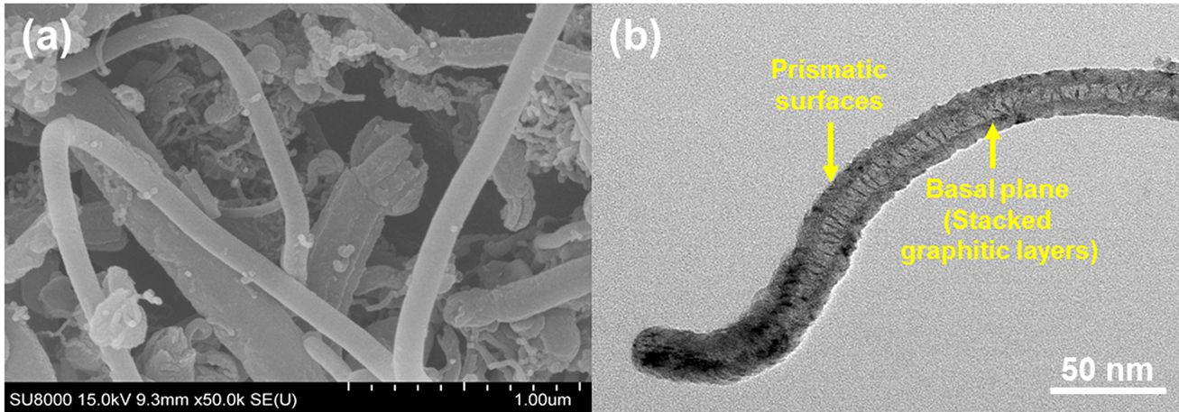
The problems associated with the low surface free energy and chemical inertness of CFs can be mitigated by introducing carbon based nanofillers, such as graphene oxide (GO), carbon black (CB), graphitic nanofibers (GNFs), carbon nanotubes (CNTs), or carbon nanofibers (CNFs), onto the CFRPs [3-5]. A multi-scale hierarchy with carbon nanomaterials has been proven to be an innovative and effective approach [6,7] that could remarkably enhance the interfacial adhesion of CFRPs by increasing the wettability and mechanical interlocking between the CFs and the epoxy matrix [8]. Especially, GNFs have been considered as promising nanofillers to reinforce CFRPs [9,10]. GNFs have attractive physical and mechanical properties with high availability among nanofillers. GNFs principally possess two different kinds of surfaces: a basal surface and prismatic surfaces. Whereas ideal basal surfaces are homogeneous and consist only of carbon layers, the prismatic surfaces are heterogeneous and contain various oxygen containing groups [11,12]. The prismatic surfaces of GNFs exhibit higher activity compared to basal surfaces, meaning that GNFs can easily be attached to the epoxy matrix. Considering the above facts, not only various functional groups on the GNFs enhance wettability with the CFRPs, but they can also act as reactive sites for further promotion of interfacial adhesion between the CFs and epoxy matrix [13,14].
The purpose of the present study is to investigate the influence of incorporating GNFs on the mechanical and interfacial properties of conventional CFRPs. As far as we know, there are no relevant studies on using GNFs as reinforcement for enhanced interfacial properties of CFRPs. Such an effort could accelerate the conversion of CFRPs into high performance materials and provide more rational guidance and fundamental understanding towards realizing the theoretical limits of interfacial properties.
2.1 Materials
Unless otherwise stated, chemicals were obtained from a commercial company and used without further purification. CFs (woven-type T-300 grade) were purchased from Toray Co., Japan. Epoxy resin (density of ~1.16 g cm−3 at 25°C and epoxide equivalent weight of 185–190 g·eq−1) was purchased from Kukdo Co., Korea. 4,4'-diaminodiphenylmethane (DDM) were purchased from Sigma-Chem Co, Korea. GNFs (herringbone type, a width of 40-50 nm and diameter of 200-300 nm) were purchased from Carbon nano-material Tech Co., Korea.
2.2 Fabrication of the composites
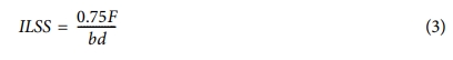
Fig. 1 illustrates the composite preparation process. First, different concentrations of GNFs (0.2, 0.4, 0.6, 0.8, or 1.0 wt%) were added to an epoxy resin/acetone mixture and ultra-sonicated for 20 min. Afterward, mixture was heated in an oven at 80°C for 15 h to remove the acetone. A curing agent (DDM) was dispersed within the mixture according to an established method using a planetary mixer. These procedures the resultant suspension was degassed in a vacuum oven at 70°C for 1 h to eliminate air bubbles. After bubble removal, the resulting suspension was continuously impregnated with CFs using a three-roll milling machine to manufacture the prepregs. Finally, the prepregs were cured at 60°C for 2 h and 120°C for 2 h, followed by 2 h of post-cure at 170°C. We denoted the specimens of GNFs/CFs/epoxy composites as GCE composites.
2.3 Characterization
The structural changes of GNFs were investigated by X-ray diffraction (XRD, Bruker Co, Korea) at room temperature with Cu-target Kα radiation (λ = 0.154 nm). The surface properties of the GNFs were investigated using a Raman microscope (Raman, Bruker Co, Korea). The surface morphologies of the prepared GNFs and GCE composites were investigated using high-resolution scanning electron microscopy (SEM, Hitachi Co, SU8010, Japen) and field-emission transmission electron microscopy (TEM, Jeol Co, USA).
2.4 Testing of the composites
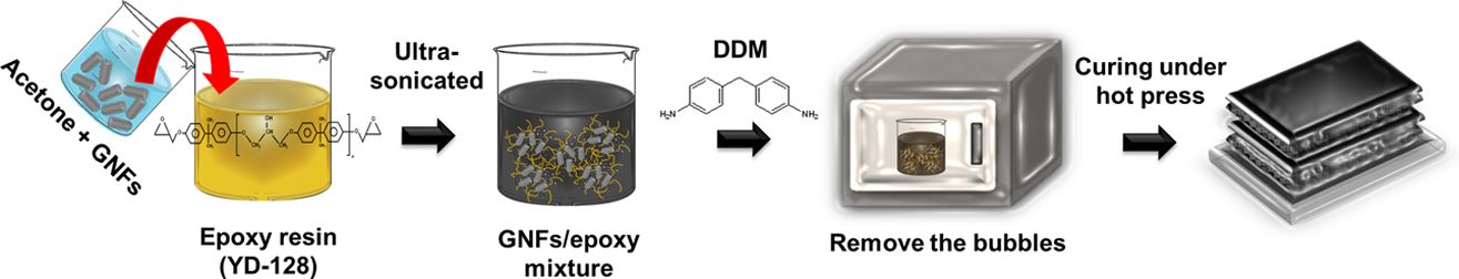
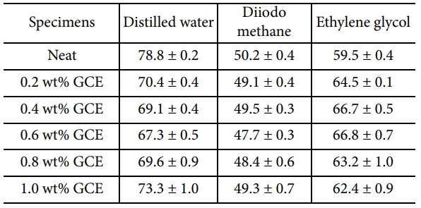
To evaluate the influence of added GNFs on the interfacial adhesion of the GCE composites, their contact angles (CA) were measured using the sessile drop method on a Rame-hart contact angle goniometer (CA, Marktech Co, Korea). At room temperature (27 ± 1°C), at least 5 valid tests were carried out and the mean value with a standard deviation lower than 1° was reported for each specimen. Standard liquid characteristics of surface free energy are shown in Table 1. According to Owens [15], Fowkes [16], and Kaelble [17], the γ is the surface free energies, γL is the London dispersion components (Lifshitz-van der Waals that includes London dispersion forces), and γSP is the specific polar components Keesom’s orientational force, dipole-induced dipole, hydrogen bonding, Debye-inductive polarization).
Universal testing machine (UTM, Lloyd-instruments Co, Lloyd LR5k, USA) was used to determine the fracture toughness (KIC) of the specimens in terms of the critical stress intensity factor, satisfying the requirements of ASTM E399. The pre-crack was obtained by lightly tapping a razor blade into the tip of the machined crack. Fracture toughness for the specimens is calculated as [18,19]:
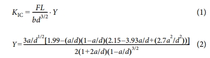
where F is the maximum loading force, L is the span between the supports, b and d are sample thickness and characteristic length of the specimen, and Y is the shape factor described in ASTM E-399. Where a is the crack length. The pre-crack was cut using a diamond razor blade (LSDC, DY Co, Korea) to approximately half the specimen depth. The interlaminar shear strength (ILSS) of the specimen was evaluated with a UTM using a three-point bending tests in accordance with ASTM D-2344. ILSS determined from the specimen was calculated as (3) [20]:
where the parameters are the same as for fracture toughness.
|
Fig. 1 A schematic of the fabrication of the GCE composites |
3.1 Characterization of GNFs
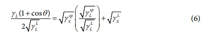
XRD analysis was performed to investigate the crystallographic nature of GNFs, the results of which are shown in Fig. 2. The XRD pattern of the GNF shows two broad peaks at 2θ = 26.2 and 43.5° corresponding to the (002) and (100) planes of the hexagonal graphitic structure, respectively [18,19].
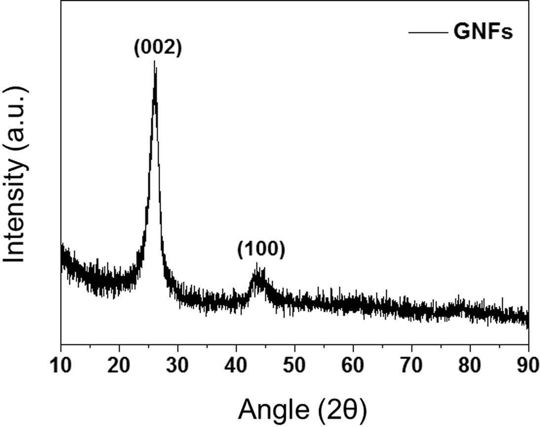
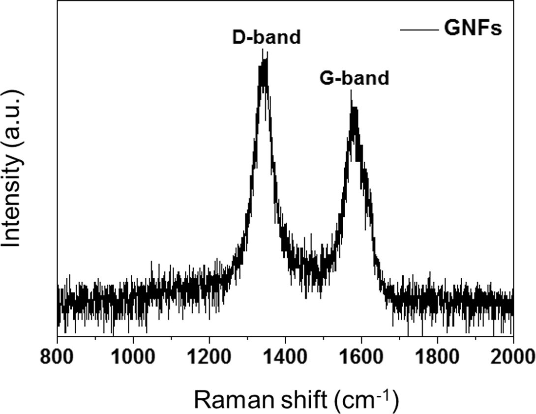
Fig. 3 presents the Raman spectra of the GNFs. The wide D-bands near 1340 cm−1 presented the prismatic surface (sp3 hybridized carbon) in the hexagonal framework of the GNF walls, representing covalent bonds of the oxygen containing groups. The small G-bands observed near 1582 cm−1 corresponded to the basal plane (sp2 hybridized graphitic layers). As a result, the prismatic surface of GNFs could be undertaken to significantly enhance interfacial adhesion.
3.2 Morphology of GNFs
The microstructures of GNFs were observed by SEM and TEM, as shown in Fig. 4(a-b). As evident in Fig. 4(a-b), the GNFs were fairly straight and highly ordered structures. The outer surface is covered by a very thin prismatic layer, whereas the inside of the nanofiber shows stacked graphitic layers of the herringbone type.
3.3 Interfacial properties of the GCE composites
The surface free energy of the composites is directly related to their interfacial adhesion. To obtain accurate surface free energy information for the composites, these values are calculated on the basis of the CAs [20-22]:
where θ is the CAs of the liquid droplet, subscript L represents the liquid, and subscript S represents a solid. Three test liquids, in conjunction with Eqs. (4) and (5), can be used to accurately determine the surface free energy with the following equation:
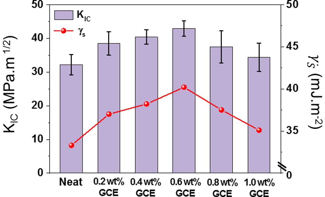
The CA and surface free energy results for the GCE composites, as calculated using Eq. (6), are reported in Table 2 and Fig. 5.
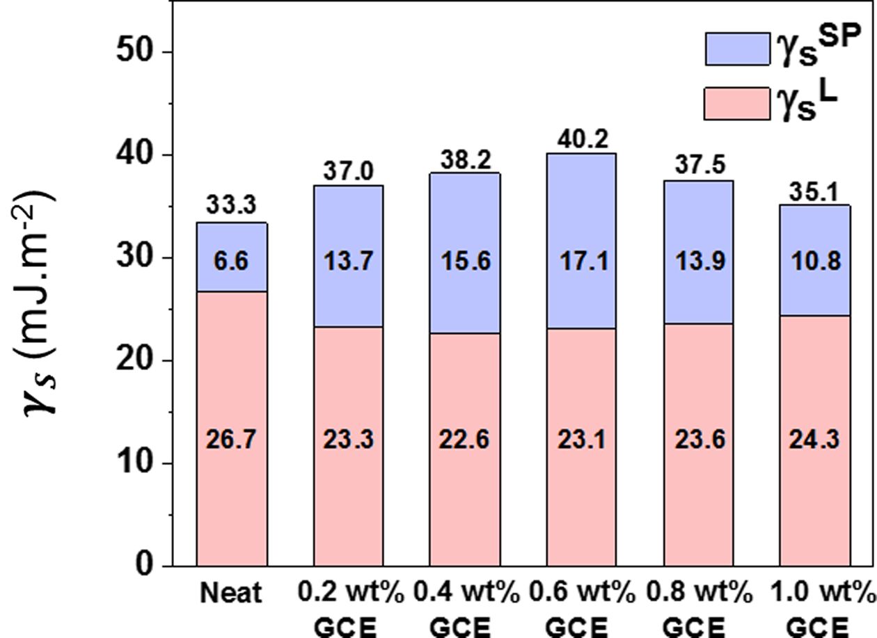
The GCE composites exhibited an obvious enhancement in comparison with neat composites. As presented in Fig. 5, the surface free energy of the GCE composites reached roughly from ~35.1 mJ·m-2 to maximum of ~40.2 mJ·m-2. As increasing GNFs contents, surface free energy is significantly increased until GCE composites. In the context of the aforementioned Raman results, GNFs showed an increase in oxygen-containing groups as a result of hybrids, which could be a major contributor to the enhancement of specific polar elements. However, when the GNFs content reached 0.8 wt%, the surface free energy and the polar component value of the composite decreases regardless. It tends to excessively bond with itself, rather than with an epoxy matrix due to its intermolecular hydrogen bonding. It should be highlighted that, in a reasonable capacity range, a higher interfacial property can be obtained by increasing the filler contents.
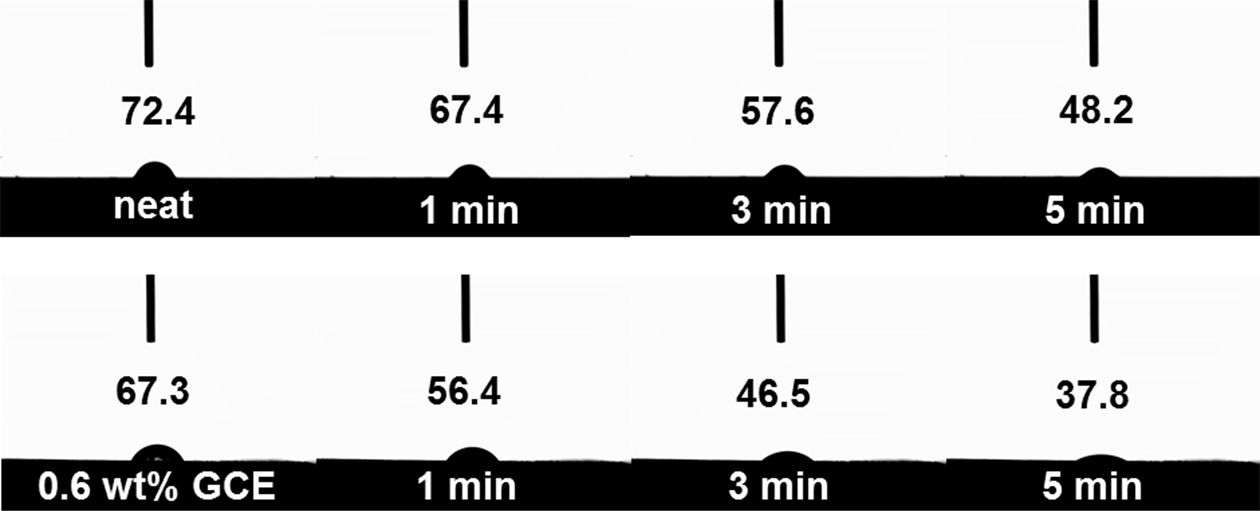
To support this explanation, we studied the wetting behavior of distilled water (carried out at 27°C for 5 min) acting on the neat and GCE composites in more detail. It can be seen in Fig. 6 that the CAs of the neat composites near 48.2° showed no obvious changes, while the CAs of the 0.6 wt% GCE composites decreased very rapidly and saturated at around 37.8°. This decrease is due to the surfaces with a large number of hydrophilic groups on the GNFs, from which water droplets could quickly diffuse, indicating that the improved interfacial interaction between GNFs and epoxy matrixes [23,24].
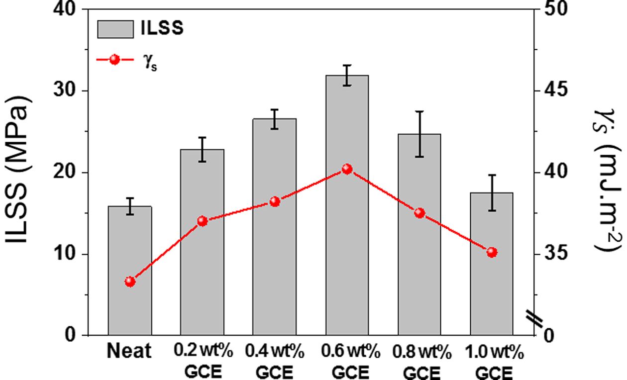
The ILSS is one of the appropriate measurements for determining the interfacial adhesion [25,26]. The out-of-plane interfacial adhesion of GCE composites was performed by ILSS defined at the interface between CFs and epoxy matrix. As illustrated in Fig. 7, the GCE composites exhibit excellent linearity for the relationship between the ILSS and surface free energy, which clearly demonstrating improved interfacial adhesion. As a result of this evaluation, the 0.6 wt% GCE composites had the highest value of ILSS 31.9 MPa, 101.9% higher than the 15.8 MPa of the neat composites. These results suggest that additional interfacial interlocking was achieved when the GNFs were included within the epoxy matrix, resulting in enhanced interfacial adhesion. Meanwhile, in the 0.8 wt% GCE composites (24.7 MPa), GNFs tended to excessively bond with itself rather than with the epoxy matrix because of its strong van der Waals force. This reduces the shear propagation energy, thus leading to a decrease in ILSS.
3.4 Mechanical properties of the GCE composites
Commonly, carbon based nanofillers, when used as a reinforcing element in an epoxy matrix, are known to enhance the KIC and are an important design factor, particularly for composites intended for application in the structural engineering industries [27-29]. As illustrated in Fig. 8, the GCE composites exhibit good linearity for the relationship between the surface free energy and KIC, which clearly demonstrating enhanced interfacial adhesion. Besides, the GCE composites exhibited significant enhancements in KIC values compared to the neat composites. Compared to the neat composites (32.2 MPa·m1/2), the KIC values of the 0.2 wt% OGCE composites (38.5 MPa·m1/2) increased by 19.6%. Moreover, the measured highest KIC value reached 42.9 MPa·m1/2 in the 0.6 wt% GCE composites, equating to enhancements of 33.2% compared to the neat composites. These results suggest that additional interfacial interlocking was achieved when the GNFs were included within the epoxy matrix, resulting in enhanced mechanical properties of composites.
We observed the fracture surfaces in more detail to study the fracture mechanisms acting on the GCE composites. As shown in Fig. 9(a), the cracks in the neat composites propagate directly through the interface of the CFs/epoxy matrix, and adhesive failure occurs. In this case, the composite shows a smooth fracture surface, which is typically a brittle fracture of the epoxy resin [30]. On the other hand, the 0.6 wt% GCE composites exhibited crack progression almost proprietarily along the GNF-rich interlayer and were tightly embedded within an epoxy matrix without de-bonding (Fig. 9(b)). This inhibits propagation through the epoxy matrix as a crack must pass either through or around areas with GNF-rich interlayers, resulting in an enhanced KIC.
|
Fig. 2 XRD patterns of the GNFs |
|
Fig. 3 Raman spectrum of the GNFs |
|
Fig. 4 Surface morphology of the GNFs: (a) SEM images of GNFs and (b) TEM images of GNFs |
|
Fig. 5 Surface free energy of the GCE composites |
|
Fig. 6 Optical images of the contact angle of water over time |
|
Fig. 7 Correlation between ILSS and surface free energy in the interfacial adhesion of GCE composites |
|
Fig. 8 Correlation between KIC and surface free energy in the interfacial adhesion of GCE composites |

|
Fig. 9 Fracture surface of GCE composites: (a) SEM images of neat composites and (b) SEM images of 0.6 wt% GCE composites |
In this study, GNFs were utilized for use as reinforcement in CFRPs. We focused on the interfacial interactions of GNFs in epoxy matrix and CFs and provided a simple approach to increase ILSS and KIC. Specifically, the ILSS and KIC of the 0.6 wt% GCE composites could reach to 31.9 MPa and 42.9 MPa·m1/2, approximately 101.9% and 33.2%, respectively, compared with those of neat composites. The presence of the GNF-rich interlayer enhanced the wettability between the CFs and the epoxy matrix, thereby inducing the formation of a new interface for efficient load transfer, which was the main reason for the enhancement of the composites.
This work was supported by the Technology Innovation Program (or Industrial Strategic Technology Development Program-Development of technology on materials and components) (20010106, Adhesives with low water permeability and low outgassing) funded By the Mistry of Trade, Industry & Energy (MOTIE, Korea) and the Technological Innovation R&D Program (S2829590) funded by the Small and Medium Business Administration (SMBA, Korea).
- 1. Robertson, I.D., Yourdkhani, M., Centellas, P.J., Aw, J.E., Ivanoff, D.G., Goli, E., and Moore, J.S., “Rapid Energy-efficient Manufacturing of Polymers and Composites via Frontal Polymerization”, Nature, Vol. 557, 2018, pp. 223-227.
- 2. Taynton, P., Ni, H., Zhu, C., Yu, K., Loob, S., Jin, Y., Qi, H.J., and Zhang, W., “Repairable Woven Carbon Fiber Composites with Full Recyclability Enabled by Malleable Polyimine Networks”, Advanced Materials, Vol. 28, 2016, pp. 2904-2909.
-

- 3. Zhang, Y., Heo, Y.J., Son, Y.R., In, I., An, K.H., Kim, B.J., and Park, S.J., “Recent Advanced Thermal Interfacial Materials: A Review of Conducting Mechanisms and Parameters of Carbon Materials”, Carbon, Vol. 142, 2019, pp. 445-460.
-
- 4. Kwon, Y.J., Kim, Y., Jeon, H., Cho, S., Lee, W., and Lee, J.U., “Graphene/carbon Nanotube Hybrid as a Multi-functional Interfacial Reinforcement for Carbon Fiber-reinforced Composites”, Composites Part B: Engineering, Vol. 122, 2017, pp. 23-30.
-
- 5. Karger-Kocsis, J., Mahmood, H., and Pegoretti, A., “All-carbon Multi-scale and Hierarchical Fibers and Related Structural Composites: A Review”, Composites Science and Technology, Vol. 186, 2020, pp. 107932.
-
- 6. Hong, H., Bae, K.J., and Yu, J., “Effect of Boron Nitride on Mechanical Properties, Thermal and Electrical Conductivities of Carbon Fiber Reinforced Plastics”, Composites Research, Vol. 33, No. 3, 2020, pp. 153-160.
- 7. Zhang, T., Cheng, Q., Xu, Z., Jiang, B., Wang, C., and Huang, Y., “Improved Interfacial Property of Carbon Fiber Composites with Carbon Nanotube and Graphene Oxide as Multi-scale Synergetic Reinforcements”, Composites Part A: Applied Science and Manufacturing, Vol. 125, 2019, pp. 105573.
-
- 8. Jiang, Z., Wang, F., Yin, J., Gong, S., Dai, Z., Pang, Y., Xiong, Y., Zhu, Z., and Li, Z., “Vibration Damping Mechanism of CuAlMn/polymer/carbon Nanomaterials Multi-scale Composites”, Composites Part B: Engineering, Vol. 199, 2020, pp. 108266.
-
- 9. Zhou, Y., Jin, P., Zhou, Y., and Zhu, Y., “High-performance Symmetric Supercapacitors Based on Carbon Nanotube/graphite Nanofiber Nanocomposites”, Scientific Reports, Vol. 8, 2018, pp. 1-7.
- 10. 1Jang, J.H., and Han, K.S., “Fabrication of Graphite Nanofibers Reinforced Metal Matrix Composites by Powder Metallurgy and Their Mechanical and Physical Characteristics”, Journal of Composite Materials, Vol. 41, 2007, pp. 1431-1443.
-
- 11. Weinstein, R.D., Ferens, A.R., Orange, R.J., and Lemaire, P., “Oxidative Dehydrogenation of Ethanol to Acetaldehyde and Ethyl Acetate by Graphite Nanofibers”, Carbon, Vol. 49, 2011, pp. 701-707.
-
- 12. 1Ferens, A.R., Weinstein, R.D., Giuliano, R., and Hull, J.A., “Selective Decomposition of Isopropanol Using as Prepared and Oxidized Graphite Nanofibers”, Carbon, Vol. 50, 2012, pp. 192-200.
-
- 13. 1Shin, P.S., Kim, J.H., Baek, Y.M., Park, H.S., and Park, J.M., “Epoxy Matrix with Adding Dopamine for Improving Mechanical Property and Interfacial Adhesion with Glass Fiber”, Composites Research, Vol. 32, 2019, pp. 96-101.
-
- 14. 1Kang, M.S., Jeon, M.H., Kim, I.G., and Woo, K.S., “The Study on the Characteristics of Mode I Crack for Cross-ply Carbon/epoxy Composite Laminates Based on Stress Fields”, Composites Research, Vol. 32, 2019, pp. 327-334.
- 15. Owens, D.K., and Wendt, R.C., “Estimation of the Surface Free Energy of Polymers”, Journal of Applied Polymer Science, Vol. 13, 1969, pp. 1741-1747.
-
- 16. Fowkes, F.M., “Determination of Interfacial Tensions, Contact Angles, and Dispersion Forces in Surfaces by Assuming Additivity of Intermolecular Interactions in Surfaces”, The Journal of Physical Chemistry, Vol. 66, 1962, pp. 382-382.
-
- 17. Kaelble, D.H., “Dispersion-polar Surface Tension Properties of Organic Solids”, The Journal of Adhesion, Vol. 2, 1970, pp. 66-81.
-
- 18. Ranganathan, N., Oksman, K., Nayak, S.K., and Sain, M., “Structure Property Relation of Hybrid Biocomposites Based on Jute, Viscose and Polypropylene: The Effect of the Fibre Content and the Length on the Fracture Toughness and the Fatigue Properties”, Composites Part A: Applied Science and Manufacturing, Vol. 83, 2016, pp. 169-175.
-
- 19. Lee, S.O., Rhee, K.Y., and Park, S.J., “Influence of Chemical Surface Treatment of Basalt Fibers on Interlaminar Shear Strength and Fracture Toughness of Epoxy-based Composites”, Journal of Industrial and Engineering Chemistry, Vol. 32, 2015, pp. 153-156.
-
- 20. Kim, S.H., Park, S.J., Rhee, K.Y., and Park, S.J., “Effects of Ozonized Carbon Black on Fracture and Post-cracking Toughness of Carbon Fiber-reinforced Epoxy Composites”, Composites Part B: Engineering, Vol. 177, 2019, pp. 107379.
-
- 21. Kim, B.J., Lee, Y.S., and Park, S.J., “A Study on Pore-opening Behaviors of Graphite Nanofibers by a Chemical Activation Process”, Journal of Colloid and Interface Science, Vol. 306, 2007, pp. 454-458.
-
- 22. Rambabu, G., Sasikala, S., and Bhat, S.D., “Nanocomposite Membranes of Sulfonated Poly (phthalalizinone ether ketone)–sulfonated Graphite Nanofibers as Electrolytes for Direct Methanol Fuel Cells”, RSC Advances, Vol. 6, 2016, pp. 107507-107518.
-
- 23. Karakaya, N., Papila, M., and Özkoç, G., “Overmolded Hybrid Composites of Polyamide-6 on Continuous Carbon and Glass Fiber/epoxy Composites: ‘An Assessment of the Interface’”, Composites Part A: Applied Science and Manufacturing, Vol. 131, 2020, pp. 105771.
-
- 24. Yang, G., Yang, T., Yuan, W., and Du, Y., “The Influence of Surface Treatment on the Tensile Properties of Carbon Fiber-reinforced Epoxy Composites-bonded Joints”, Composites Part B: Engineering, Vol. 160, 2019, pp. 446-456.
-
- 25. Kim, S.H., Heo, Y.J., Park, M., Min, B.G., Rhee, K.Y., and Park, S.J., “Effect of Hydrophilic Graphite Flake on Thermal Conductivity and Fracture Toughness of Basalt Fibers/epoxy Composites”, Composites Part B: Engineering, Vol. 153, 2018, pp. 9-16.
-
- 26. Park, S.M., Kim, D.W., Jeong, G., Lim, J.H., and Kim, S.W., “Prediction and Calibration of Transverse Mechanical Properties of Unidirectional Composites with Random Fiber Arrangement Considering Interphase Effect”, Composites Research, Vol. 32, 2019, pp. 270-278.
- 27. Han, S.H., Lee, J.W., Kim, J.S., Kim, Y.M., Kim, W.D., and Um, M.K., “A Study on Manufacturing Method of Standard Void Specimens for Non-destructive Testing in RFI Process and Effect of Void on Mechanical Properties”, Composites Research, Vol. 32, 2019, pp. 395-402.
- 28. Kang, W.S., Rhee, K.Y., and Park, S.J., “Influence of Surface Energetics of Graphene Oxide on Fracture Toughness of Epoxy Nanocomposites”, Composites Part B: Engineering, Vol. 114, 2017, pp. 175-183.
-
- 29. Liu, B., Cao, S., Gao, N., Cheng, L., Liu, Y., Zhang, Y., and Feng, D., “Thermosetting CFRP Interlaminar Toughening with Multi-layers Graphene and MWCNTs under Mode I Fracture”, Composites Science and Technology, Vol. 183, 2019, pp. 107829.
-
- 30. Kilic, U., Sherif, M.M., and Ozbulut, O.E., “Tensile Properties of Graphene Nanoplatelets/epoxy Composites Fabricated by Various Dispersion Techniques”, Polymer Testing, Vol. 76, 2019, pp. 181-191.
-
 This Article
-
2021; 34(2): 82-87
Published on Apr 30, 2021
- 10.7234/composres.2021.34.2.082
- Received on Nov 30, 2020
- Revised on Jan 11, 2021
- Accepted on Mar 30, 2021
Services
- Abstract
1. introduction
2. experimental
3. results and discussion
4. conclusions
- Acknowledgements
- References
- Full Text PDF
Shared
Correspondence to
- Soo-Jin Park
-
Department of Chemistry, Inha University, Incheon 22212, Korea
- E-mail: sjpark@inha.ac.kr
Gangnam Mirae Tower, Suite 601, 174 Saimdang-ro, Seocho-gu, Seoul 06627, South Korea
Tel: +82-2-598-1550 Fax: +82-2-598-1557 E-mail: composites@kscm.re.kr